


Updated April 24, 2023
In this application note, we outline the essential aspects of the PDH laser locking method and the practical use of the Moku:Lab Laser Lock Box instrument to realize a PDH laser locking system. This method is also compatible with Moku:Go and Moku:Pro Laser Lock Boxes.

Pound-Drever-Hall laser locking with Moku:Lab
Locking a laser by forcing the laser and reference frequency to be equal allows for two scenarios: (1) the locking system steers the laser frequency to be equal to the reference frequency, which is referred to as frequency stabilization; and (2) the locking system forces the reference frequency to follow the laser frequency, which is referred to as frequency tracking. Whether used for frequency stabilization or frequency tracking, Liquid Instruments’ Laser Lock Box is designed to assist in high-performance, high-gain laser locking systems. The Moku:Lab Laser Lock Box offers advanced setup, acquisition and diagnostic features that makes it easier and quicker to set up and characterize laser locking systems.
Basics of laser locking and the PDH technique
At the core of any laser locking technique is the measurement that provides the difference, or error, between the laser and a frequency reference. Often termed the ‘error signal’, the quality of this signal ultimately determines the precision and accuracy of the entire locking system. Arguably one of the most precise methods for obtaining an error signal is the Pound-Drever-Hall (PDH) technique. Using the PDH error signal in feedback systems has proven to give an extremely accurate and precise measure of changes in the laser or cavity, resulting in its use in a myriad of applications such as absorption spectroscopy and gravitational wave detection. The PDH error signal technique has several key advantages such as:
- The technique provides highly accurate and precise measures of phase and frequency differences between the laser and the cavity resonance.
- The sensing technique provides a zero-crossing error signal with zero frequency difference corresponding to a null error signal.
- Assuming all signal processing is done digitally, it avoids low frequency noise generated in analog electronics and demodulation circuits
These advantages do come at some cost. To obtain such a precise measure of the frequency/phase, the PDH technique utilizes radio-frequency modulation and demodulation techniques. This adds considerable complexity to the signal processing system as well as some complexity to the optical system. But once understood, these complexities are minor compared to the advantages of the PDH systems.

Laser Locking using the Moku:Lab Laser Lock Box
The Moku:Lab Laser Lock Box aims to drastically reduce the complexity usually associated with operating and using a PDH locking system. Figure 1 illustrates an example setup of a PDH laser locking system. The setup uses a solid state Nd:YAG NPRO laser, which is aligned and mode-matched to a moderate finesse cavity. The Moku:Lab Laser Lock Box was subsequently used to produce all the signals required to lock the laser to the cavity resonance.
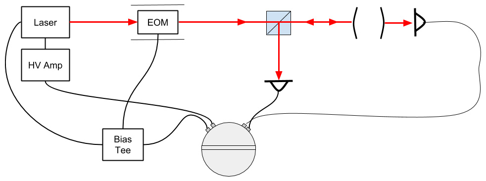
Figure 1: Example of PDH laser locking system
Locking a laser consists of:
- Setting up the system (including alignment).
- Modulating the laser
- Centering the resonance
- Obtaining an error signal
- Locking the laser
- Optimizing the lock
Setting up the system
For the system to be operating optimally, it is important to ensure that the laser beam is well aligned with the optical axis of the cavity and that the mode of the laser matches well with the spatial mode of the resonator. It is important to note that misalignment or mode-mismatches can result in reduced locking performance or, in extreme cases, the system not working at all. Finally, the system is monitored using two photodetectors; one photodetector receives light that is reflected back off the cavity, and the other one receives light that has passed through the cavity.
Connecting the Moku:Lab Outputs
To produce a successful PDH lock, several signals need to be generated.
- The modulation signal; sent to the EOM to produce phase modulation sidebands.
- The primary feedback signal; in this case feedback to the PZT frequency controls of the laser. To drive the PZT of the laser, a high voltage amplifier (HV amp) was used.
- The secondary feedback signal (Optional); used to feedback to the thermal controls of the laser. Temperature feedback generally has greater range but slow and coarse tuning software.
In this case, the modulation signal and the secondary feedback signals were generated on output 2 of the Moku:Lab and separated using a Bias-Tee.
Connecting the Moku:Lab Inputs
The reflected signal from the photodetector generally contains all the information needed to create a feedback signal. This signal is connected to input 1 for most of the signal processing. The second input channel is able to monitor any secondary auxiliary signals.
- Input 1 is used as the main channel for most signal processing. In this system the AC output of the photodetector was connected to input 1 of the Moku:Lab.
- The DC component of the transmitted signal was connected to input 2. Although not necessary, the DC signal helps identify and optimize features in the locking system.
Modulating the laser
Phase modulation in this case is achieved by applying a sinusoidal voltage signal to the EOM.
A modulation signal can be produced by utilizing the Aux oscillator feature. For this system we will use a 10 MHz modulation tone.
- Set the Aux oscillator to 10 MHz.
- Set the Amplitude of the Aux oscillator. Be sure to choose a voltage that is within the EOM specifications. In this case we set the amplitude to 100 mV.
- Choose the Aux Oscillator output. In this example, set the Aux Oscilloscope to output 2.
- Switch the output on.
Scanning the Laser Frequency and finding a resonance
Scanning the laser frequency greatly helps characterize and optimize signals for locking.
A scanning feature is integrated into the Moku:Lab Laser Lock Box. In this example we set the scan generator to output a signal to the PZT actuator (output 1). To do this:
- Set the scan to a triangle waveform
- Set the amplitude to 500 mV
- Choose which output to send the Scan signal to. In this example the output channel is set to output 1
- Switch the output on

Figure 2: Auxiliary oscillator is used to drive the EOM and create phase modulation sidebands.
Centering the system resonance
To make things easier while setting up a laser lock, we can usually center the resonance in the middle of the scan and adjust the offsets applied to the temperature controller.
Adjust the offset to the temperature until the resonant feature occurs at 0 on the scan.
Getting and Optimizing the Error Signal
To get an error signal, the RF signal received from the photodetector needs to be demodulated with the local oscillator. Selecting the correct phase of the local oscillator is critical to optimize the error signal. To do this, adjust the phase of the local oscillator whilst observing the error signal.
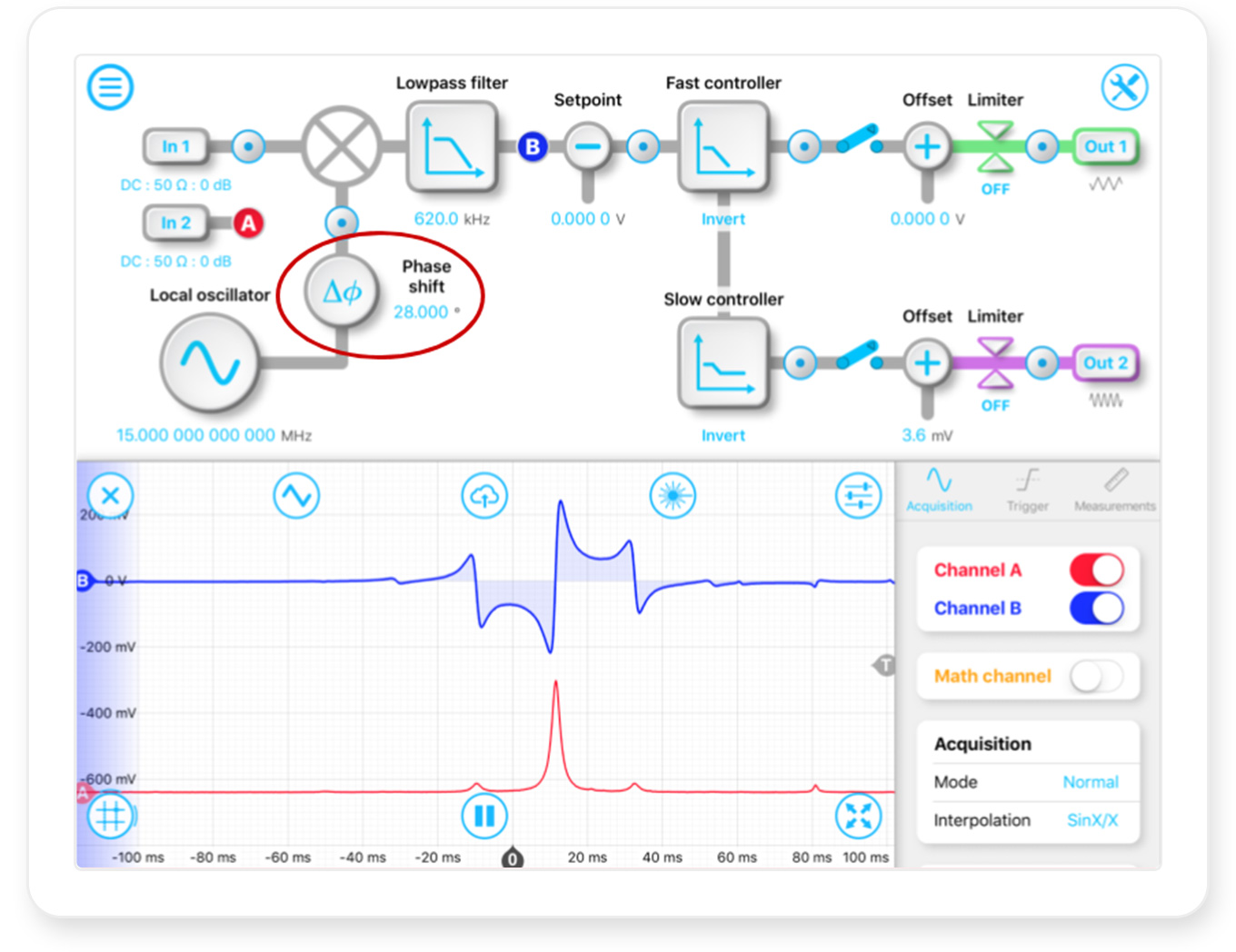
Figure 3: Channel A and B showing transmitted response of the cavity and error signal recovered from the cavity respectively.
Locking the Laser
Manually locking the laser
- Center the resonance on the scan.
- Set the fast PID controller. (it may be useful to just use an integrator with a ~10 Hz pole as the response can be optimized later)
- Turn on the PID controllers
- Slowly decrease the scan amplitude until the laser power is at maximum.
- Turn off the scan
Using Tap-to-Lock
- Center the resonance on the scan.
- Set the fast PID controller. (it may be useful to just use a integrator with a ~10 Hz pole as the response can be optimized later)
- Select tap to lock mode
- Tap on the resonance that you want to lock to
Note: Make sure that the direction of the feedback is correct.
Adjusting and optimizing your lock
Once the system is locked, we can optimize the lock.. This generally means adjusting the gains in the PID controller.
To do this open the PID controller menu:
- Increase the proportional gain slightly until the system begins to oscillate.
- Reduce the proportional gain slightly until the system stops oscillating
- Repeat this for the integrators and differentiators (if necessary)

Figure 4: When the laser is locked, the transmitted power (Channel A) will be at its constant maximum.
The error signal (Channel B) will also be held at zero.
Conclusion
The Moku:Lab Laser Lock Box provides an all-in-one laser locking instrument with intuitive controls. By replacing stand-alone waveform generators, phase shifters, demodulators, filters and PID controllers, Moku:Lab enables a high performance laser locking solution.
Reference
[1] Danielle M. R. Wuchenich, Christoph Mahrdt, Benjamin S. Sheard, Samuel P. Francis, Robert E. Spero, John Miller, Conor M. Mow-Lowry, Robert L. Ward, William M. Klipstein, Gerhard Heinzel, Karsten Danzmann, David E. McClelland, and Daniel A. Shaddock, “Laser link acquisition demonstration for the GRACE Follow-On mission,” Opt. Express 22, 11351-11366 (2014)
[2] Moku:Lab Arbitrary Waveform Generator user manual at https://liquidinstruments.com/products/integrated-instruments/waveform-generator/