


Bit resolution and sampling rate are two of the most important characteristics of an analog-to-digital converter (ADC). With a higher bit resolution, the input signal can be digitized with a higher resolution and lower quantization noise. Therefore, it helps improve the overall outcome of the entire digital signal processing (DSP) workflow. Most ADCs are designed to have a fixed native bit resolution and sampling rate. However, some digital instruments, such as digital storage oscilloscopes, are used to analyze a wide variety of input signals. A fixed bit resolution and sampling rate input is not always the most effective way to process the data. In this application note, we will introduce the concept of how oversampling can effectively increase the bit resolution of an input signal, and how Moku:Go’s and Moku:Lab’s onboard signal processing schemes automatically implement this technique to improve the measurement result.
Moku:Go
 Moku:Go combines 15+ lab instruments in one high performance device, with 2 analog inputs, 2 analog outputs, 16 digital I/O pins and optional integrated power supplies.
Introduction
In the past few decades, the semiconductor fabrication process has improved exponentially. The number of transistors that can fit into a certain area has increased by several orders of magnitude. Many signal processing devices, such as audio recording and playback instrumentation, have transitioned from the analog realm to the digital realm as the computational power of DSP chips increased in tandem with steady cost reductions. The DSP-based devices also have a simpler structure: the ADCs are first used to convert the signal to the digital domain. The DSP chip processes the signal in the digital domain, then sends the result to the digital-to-analog converters (DACs) to generate the analog output. While many devices are equipped with application-specific integrated circuits (ASIC) for DSP, the evolution of field-programmable gate array (FPGA) further improves the flexibility of the ADC-DSP-DAC architecture, enabling multiple DSP workflows to be implemented on the same hardware. Liquid Instruments’ Moku platforms utilize Xilinx’s system on a chip (SoC) and FPGA architecture to integrate up to twelve test and measurement instruments on a single device. With a simple click on the user interface, different instruments can be deployed within a few seconds. Moku platforms provide a seamless experience for a variety of workflows, from undergraduate engineering labs to government research labs and commercial engineering spaces.
Analog to digital conversion is an essential step for high-quality measurement. ADCs sample a voltage signal from a device or sensor, then convert this analog signal to a digital signal with a certain number of bits. The bit resolution along with its sampling rate are the two of the most important characteristics of an ADC. With a higher number of bits, the input analog signal can be represented with a higher resolution. For example, given a 2 Vpp input range, an 8-bit ADC provides the minimum quantization step of 2/28≈7.81 mV. A 12-bit ADC provides the minimum quantization step of 2/212≈0.488 mV. Therefore, a higher number of bits improves the measurement accuracy. On the other hand, high-resolution ADCs significantly increase the DSP data throughput. Given a fixed performance of a DSP chip, the native bit resolution of the input is sometimes limited by the maximum sampling rate. Some of the processing power may be wasted when the input contains only the low-frequency components, where a high sampling rate is not needed. To improve the effectiveness of the DSP on Moku hardware, oversampling techniques are implemented in many Moku instruments. This method sacrifices a certain amount of effective sampling rate and improves the effective number of bits (ENOB), ensuring the processing power is always utilized most efficiently. In this application note, we will introduce how oversampling can effectively increase the bit resolution of an input signal and how some of the instruments available on Moku hardware utilize the FPGA architecture to automatically implement this technique to achieve more precise measurements.

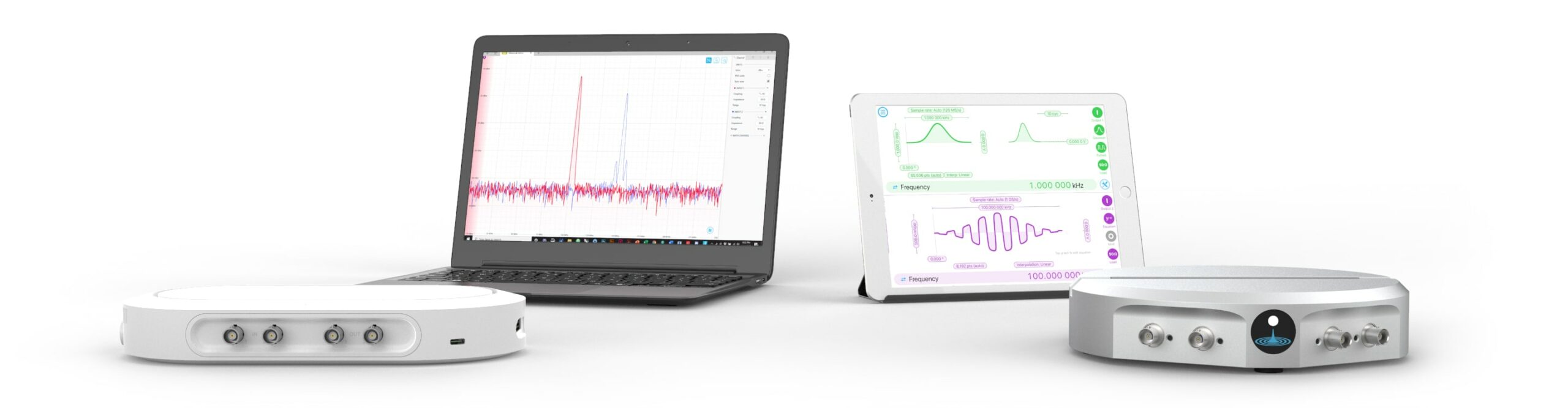
Figure 1: Liquid Instruments’ FPGA-based Moku:Go (left) and Moku:Lab (right) test and measurement platforms
An intuitive demonstration of oversampling
Oversampling is a process of averaging n consecutive samples in the time domain down to a single data point, then sending the data point downstream for further DSP. It reduces the sampling rate by a factor of n. To get an intuitive understanding of how averaging increases the resolution, let us first do a quick recap on ADC.
The ADC circuit measures the analog input at a certain sampling rate and converts the input voltage to a binary number based on the input level. Let us imagine that we have a 2-bit ADC with a full dynamic range from 0 V to 1V. Figure 2 shows a simplified block diagram of a 2-bit ADC (left), and the output binary number as a function of the input level.
Once the arbitrary waveforms are loaded into the lookup table, we can deploy them to the Moku:Go and start generating signals.

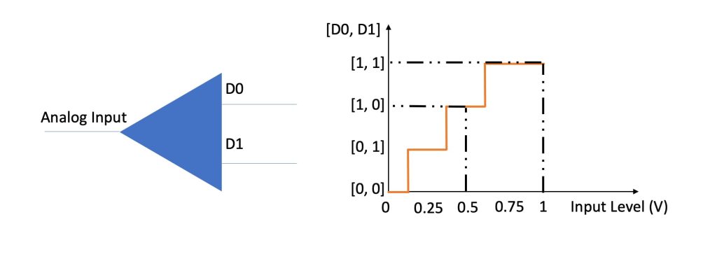
Figure 2: A simplified block diagram of an ADC (left) and the binary output of the ADC (y-axis), as a function of input level (x-axis)
With this 2-bit ADC input, we assume voltages in ranges of 0 to 0.125 V, 0.125 to 0.375 V, 0.375 to 0.625 V, 0.625 to 1 V result in, [0, 0], [0, 1], [1 ,0], and [1, 1] digital output, respectively. If the ADC gives [1, 0] as the output, we estimate the input voltage as 0.5 V. If the actual input voltage is 0.4, the 0.1 V difference is called quantization error. To reduce the quantization error, a measurement with a higher ENOB is required.
Now, let us take a closer look at how averaging improves the resolution. In the real world, the input voltage at the ADC contains a certain level of noise. For demonstration, we assume the noise can be approximated by white Gaussian noise and centered around 0.4 V. By acquiring multiple samples from the ADC, a histogram of the output can be plotted.
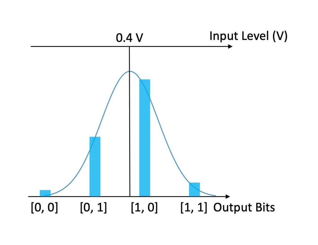
Figure 3: A graphical illustration of an input signal with a Gaussian distribution, centered at 0.4 V. The blue bars represent a possible histogram of the ADC output counts after measuring certain number of samples.
Although most of the sample points fall into the [1, 0] bin (0.5 V), a certain number of sample points give the reading of [0, 1] (0.25 V). If we take the average, the result is in between 0.25 V and 0.5 V, and leaning toward 0.5 V. Therefore, it effectively increases the resolution of the 2-bit ADC and a more accurate result can be estimated.
However, there are a few important remarks: This method works if the noise is white, Gaussian-like noise and the noise is sufficient to move the input to two adjacent bits. Otherwise, oversampling may not be effective. The ENOB of a system that satisfies these conditions grows one bit every four-fold the system oversamples. This relation can be described by the following equation, where 𝑓ADC is the native sampling rate of the ADC, and 𝑓S is the effective sampling rate after averaging.

A more detailed derivation of this equation can be found in chapter 12 of the following book:
Li, Tan. Digital Signal Processing. Academic Press, 2008
Implementation of oversampling in Moku instruments
The oversampling technique is automatically implemented in various DSP steps on every Moku instrument. In this application note, we will use Moku:Go’s Data Logger and PID Controller to demonstrate the improvement via oversampling.
Moku:Go’s Data Logger
Moku:Go is equipped with a 12-bit ADC with a 10 or 50 Vpp input range. At 10 Vpp, the minimal resolution is calculated by 10/212, which equals 2.44 mV. By selecting the precision mode in the Data Logger, the instrument automatically oversamples the input with the selected input sampling rate. In this experiment, we connected a waveform generator to Moku:Go’s input with a 0 V DC output. Then, we manually stepped up the DC voltage, 1 mV per step, at approximately 10 second intervals. We logged the data at 10 Sa/s sampling rate.
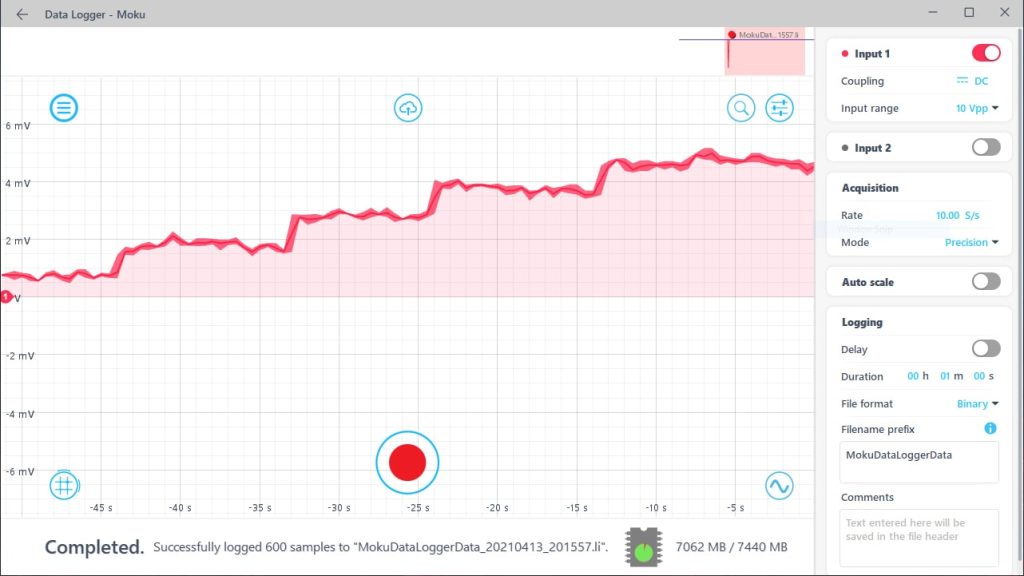
Figure 4: A step function with 1 mV increments was acquired by Moku:Go data logger.
The data trace was transferred to the computer as a .CSV file. The voltage readings were plotted as a function of time. Despite the 12-bit native resolution, the voltage steps were clearly resolved (Figure 5).
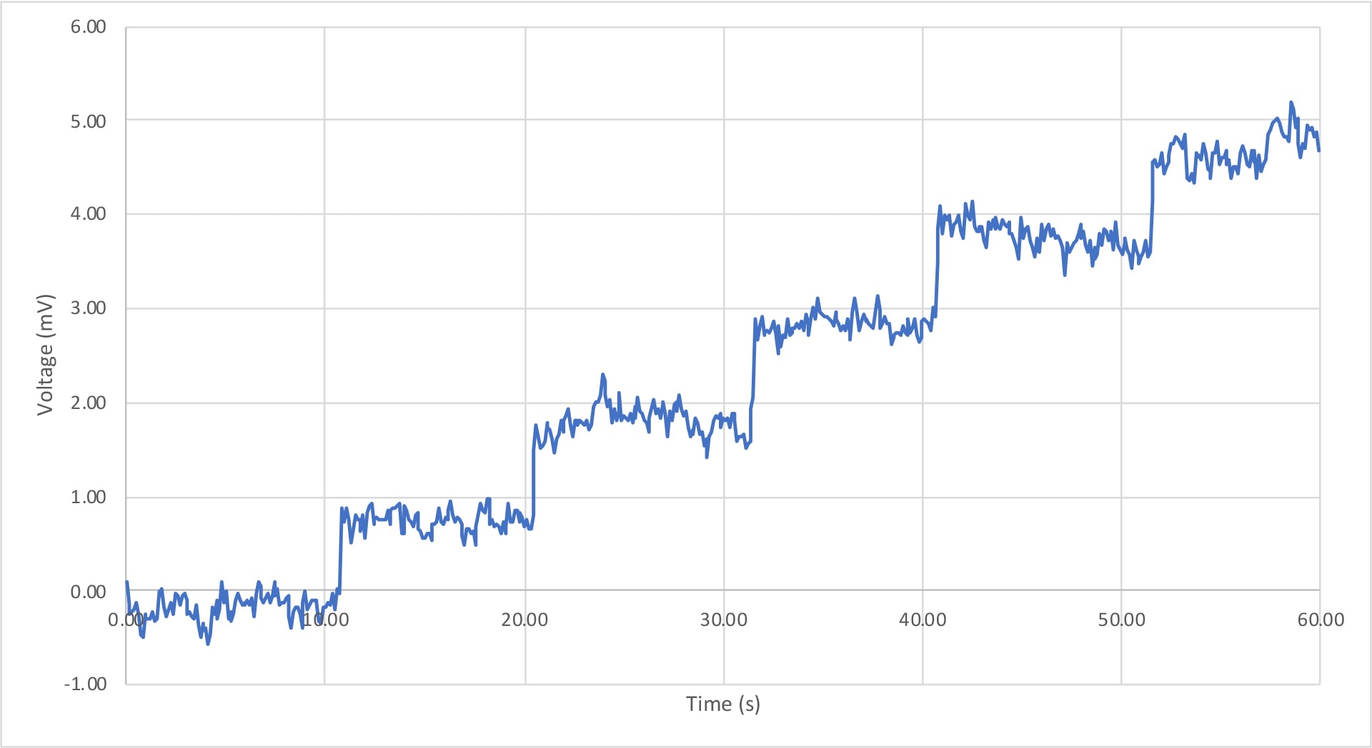
Figure 5: With automatic oversampling, 1 mV increments were clearly resolved by Moku:Go
Moku:Go’s PID Controller
A PID controller is a commonly used component for closed-loop control systems. Moku:Go’s onboard FPGA DSP capability allows the PID Controller to have a <30° at 20 kHz. It is suitable for certain high-bandwidth applications. Given the PID’s phase lag, a sampling rate of a few MHz is sufficient to cover all the frequency components. Based on the equation given in the previous section, there is room for additional ~ 2 bits vertical resolution. The effective minimal quantization step can be reduced below 1 mV. In this experiment, we demonstrated how Moku:Go PID automatically performed oversampling to increase the measurement accuracy beyond ADCs’ native resolution. We turned off the integrator and differentiator of the PID controller and applied a 40 dB proportional gain. Any input signals were amplified by 100X. Next, we enabled the probe points at the PID’s output and fed in a similar DC step signal with 1 mV steps (Figure 6).
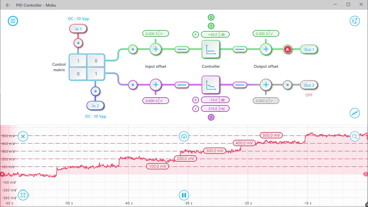
Figure 6: Moku:Go PID controller automatically oversampled the input and outputted the signal with 100 mV increments after the 40 dB proportional gain.
The output was displayed on the built-in oscilloscope. Despite the 2.44 mV native resolution, the PID Controller was able to resolve signal with 1 mV steps.
Conclusion
Oversampling is an effective way to overcome the native bit resolution for digital input, with the tradeoff of a reduced sampling rate. The real-time data processing capability of FPGA allows us to implement this technique seamlessly into various Moku instruments, providing more accurate measurements in many applications.
Reference
[1] Li, Tan. Digital Signal Processing. Academic Press, 2008
Have questions or want a printable version?
Please contact us at support@liquidinstruments.com