






This lab tutorial discusses a typical undergraduate electronics lab exercise and how it can be effectively conducted using Moku:Go and its Windows and macOS app while teaching the fundamentals of charging and discharging capacitors within a circuit. This lab was created in conjunction with the University of Detroit-Mercy.

Moku:Go
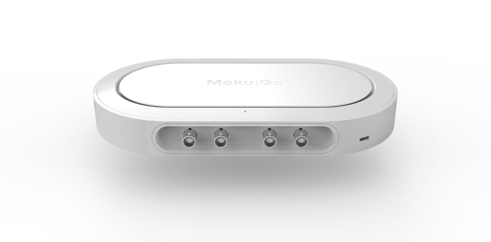
Moku:Go combines 15+ lab instruments in one high performance device, with 2 analog inputs, 2 analog outputs, 16 digital I/O pins and optional integrated power supplies.
Introduction
The oscilloscope is one of the most used tools for electrical engineers throughout their undergraduate education and in their professional careers. This lab is designed to introduce the oscilloscope and programmable power supplies to undergraduates in intro-level circuit analysis courses. You will be using Moku:Go to complete this lab which covers the charging and discharging transients of a capacitor. Figure 1 below shows an image of what measurement in Moku:Go’s Oscilloscope looks like. The purpose of this lab is not only an introduction to an oscilloscope but an introduction to the charging and discharging of capacitors. Capacitors are one of the fundamental components in circuits and understanding their various properties is vital to being a successful engineer. One of the most well-known properties of capacitors is that they can store energy in the form of a voltage difference across their plates. However, it takes a non-zero amount of time for this energy to be stored in the capacitor, which is actually a very useful feature when designing timing circuits or power control circuits. The time it takes for a capacitor to be charged to a specified voltage is further studied in this lab tutorial.
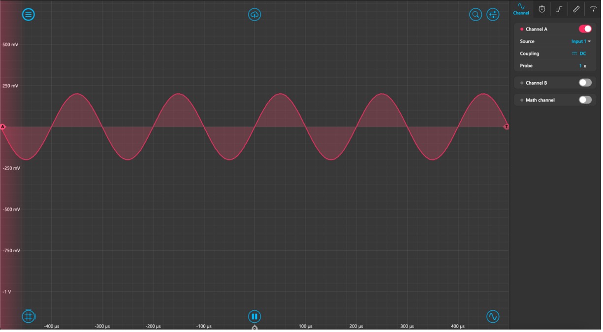
Figure 1: Oscilloscope Image
Pre-lab Exercise
1
The first exercise is to become familiar with the expression for a charging capacitors transient voltage. Figure 2 below shows a circuit with a charging capacitor and a switch that closes at t = 0s. Using KVL, solve for the voltage across the capacitor VC(t). Hint: recall the equation for current through a capacitor i=C(dv/dt)
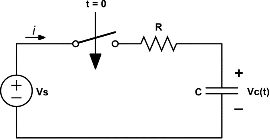
Figure 2: Charging Capacitor Design
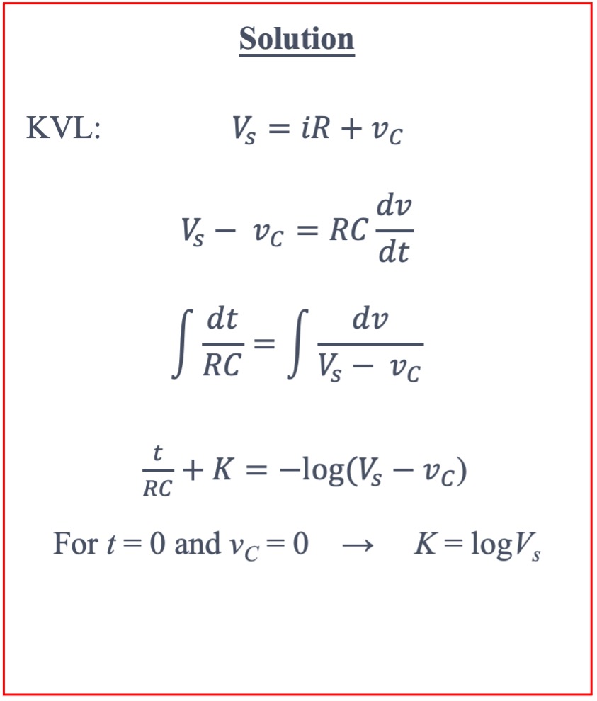 This exercise is important for developing fundamental engineering skills like deriving equations for a circuit from KVTL to understand how it will operate under test.
2
Repeat the previous exercise, except now for a discharging capacitor. Figure 3 below shows a circuit with a discharging capacitor and a switch that opens at t = 0s.
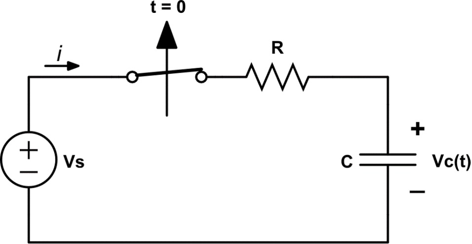
Figure 3: Discharging Capacitor Diagram
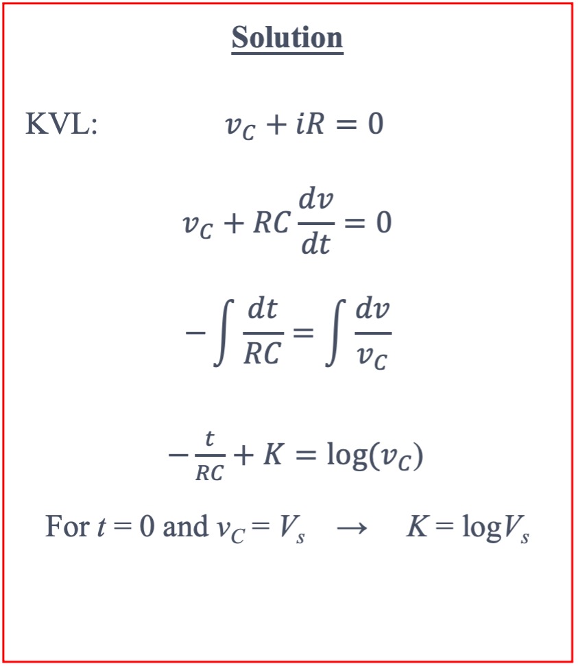 This exercise is important for developing fundamental engineering skills like deriving equations for a circuit from KVL to understand how it will operate under test. It may be useful to have students derive this formula using various combinations of R and C in series or parallel.
3
Use the following values for the charging circuit in Figure 2. Find VC when t = 1ms
- VS = 15.5 V
- R = 330Ω
- C = 10 μF
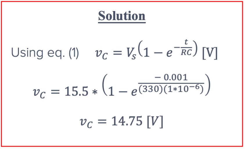
This exercise is good for applying the derived equations and confirming experimental values with expected results during the experiment. Using the same values and your calculations from Exercise 1, calculate
- The initial voltage across the capacitor, VC(0)
- The final voltage across the capacitor, VC(∞)
- The time constant, τ
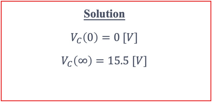
This exercise is useful for applying theory from the classroom about time constants and for developing engineering intuition.
Experimental Setup
Components
- Moku:Go [1x]
- Resistor 330Ω [x2]
- Resistor 1kΩ [x2]
- Capacitor 10μF [x1]
- Breadboard [x1]
Lab Procedure
1
Construct the circuit from Figure 4 using R1 = R2 = 330 Ω and C = 10μF.
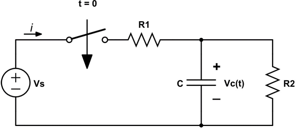
Figure 4: Charging Capacitor Lab Circuit How does R2 impact the time constant τ and the final voltage VC compared to your pre-lab exercises? This is a great exercise for students in this lab as it brings in some basic circuit theory like a voltage divider to show how it impacts the circuit’s time constant and final voltage. Students should find that the time constant decreases which results in a decrease in the time it takes for the capacitor to reach its final voltage. Subsequently, the final voltage is reduced by a factor of 2 due to the voltage divider using two 330Ω resistors in parallel.
2
Ensure you have the latest version of the Moku: desktop app downloaded on your computer. You can download the software from here.
3
Plug in the magnetic power adapter to your Moku:Go and wait for the front LED to turn green. Moku:Go can be connected to your laptop in three different ways: ethernet, USB-C, or Wi-Fi. Please refer to the Moku:Go Quick Start Guide on how to connect your Moku:Go to your computer. Once connected, Moku:Go will show up in the device select screen of the Windows or MacOS application.
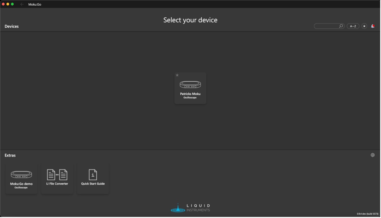
Figure 5: Moku App Device Selection Screen
4
Now that your Moku:Go is connected, double-click on the oscilloscope instrument. There will be five different tabs on the right controls drawer; these access the Channel, Timebase, Trigger, Measurement, and Voltmeter settings.
- Set the trigger mode to single. This allows you to capture a single transient waveform.
- Enable Channel 1 and the source to Input 1.
- Select edge for the trigger type and rising or falling for the charging and discharging exercises.
5
To apply a voltage source to your circuit, navigate to the main menu button

in the top left of the screen and click “Power Supply.”
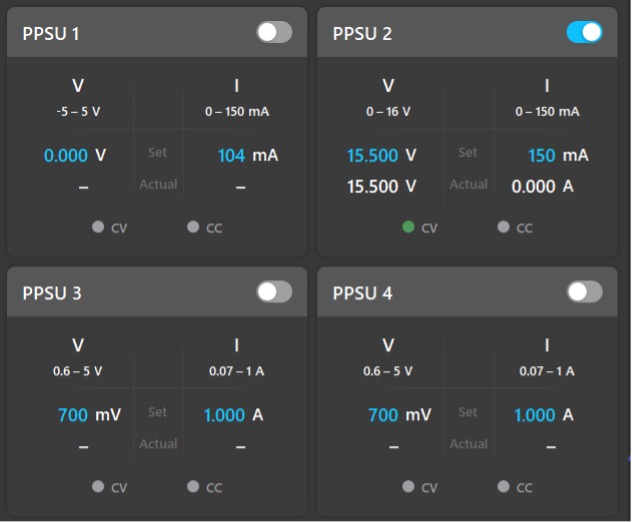
Figure 6: Power Supply Settings Ensure that PPSU 2 is turned on and set to 15.5V.
6
Capture the charging capacitor’s transient voltage waveform on Moku:Go’s Oscilloscope. Navigate to the trigger tab again and locate the trigger level setting. The trigger level is used for centering the waveform on the scope display. If the trigger level is in between the initial and final voltage, the charging waveform will be centered on the display at t = 0s at the instant the charging voltage crosses the trigger level. For this lab, it is helpful to set the trigger level to the RC time constant of the circuit. You can calculate the value using Equation 1 which should be about 63.2% of the final voltage. Figure 7 below shows an example of what the oscilloscope display should look like for a charging capacitor.
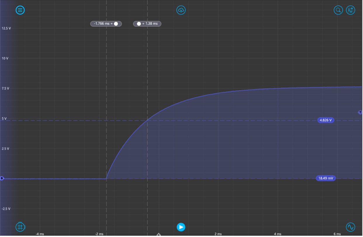
Figure 7: Oscilloscope Display of a Charging Capacitor Once your plot is similar to Figure 7, use the cursors to measure the following:
- The initial voltage across the capacitor, VC(0). Make this the reference voltage cursor.
- The steady state voltage across the capacitor, VC(∞).
- The time constant, τ1. (i.e. the time from when the switch is closed to when VC(t) = 0.632*VC(∞) ).
- The instantaneous voltage across the capacitor after one time constant, VC(τ1)
7
Repeat step 6, but for the discharging capacitor’s transient voltage. For the discharging circuit, make sure that the edge type is set to falling as the voltage will start to fall immediately after the switch is opened. Repeat the same process for determining the trigger level, but this time multiply the initial voltage by 36.8% to get the optimal value. Figure 8 below is what the plot should look like.
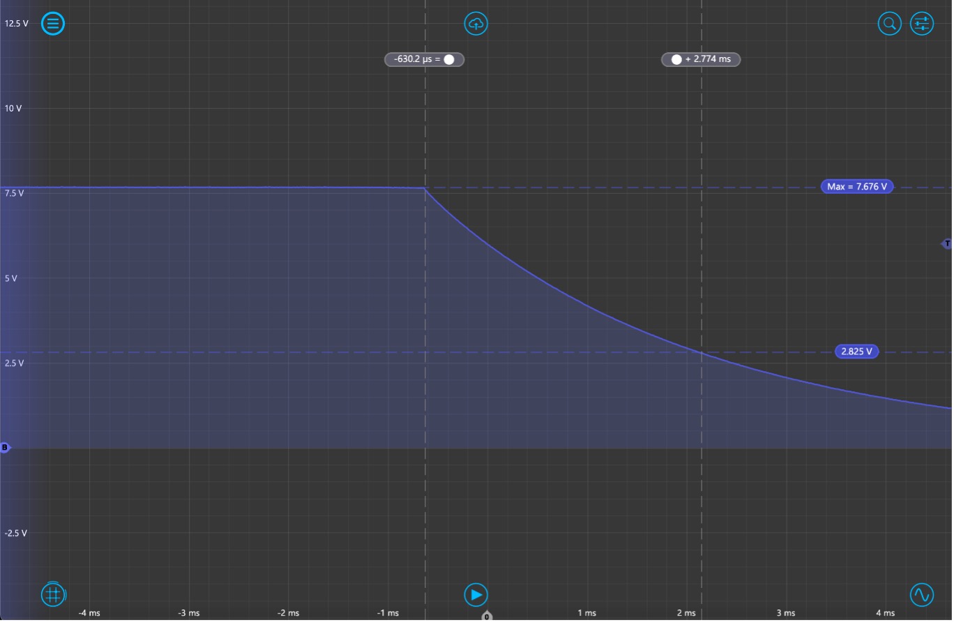
Figure 8: Oscilloscope Display of a Discharging Capacitor Once the plot is similar to Figure 8, use the cursors to measure the following:
- The initial voltage across the capacitor, VC(0). Make this your reference voltage.
- The steady state voltage across the capacitor, VC(∞).
- The time constant, τ2. (i.e. the time from when the switch is closed to when VC(t) = 368*VC(0) ).
- The instantaneous voltage across the capacitor after one time constant, VC(τ2)
8
Repeat steps 6 and 7 with the following values. Do Equations 1 and 2 still hold?
- Vs = 5v
- R1 = R2 = 1kΩ
- C = 10 μF
Summary
this lab on first order transient circuits is a great introduction to electrical engineering instrumentation and practical lab skills. The Moku: platform has many instruments at its disposal and this lab used a unique combination of the Oscilloscope and one of the four integrated programmable power supplies. The publishing and reporting of the results are easily done with screen capture or file sharing within the Moku: app. You can do this by clicking the cloud icon at the top of your screen. The screenshot below shows you how to save your results.
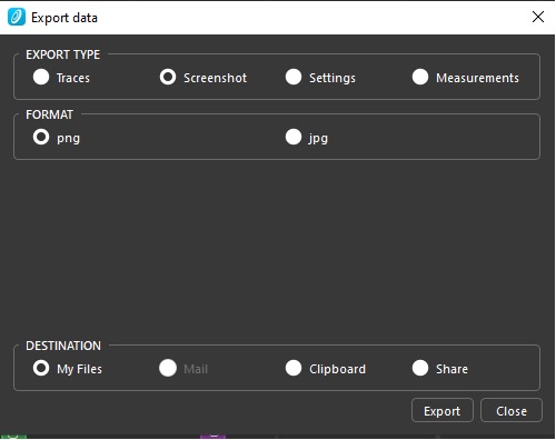
Figure 9: Oscilloscope Data Export
Benefits of Moku:Go
For the educator & lab assistants
- Efficient use of lab space and time
- Ease of consistent instrument configuration
- Focus on the electronics not the instrument setup
- Maximize lab teaching assistant time
- Individual labs, individual learning
- Simplified evaluation and grading via screenshots
For the student
- Individual labs at their own pace enhance the understanding and retention
- Portable, choose pace, place and time for lab work be it home, on campus lab or even collaborate remotely
- Familiar Windows or macOS laptop environment, yet with professional grade instruments
Moku:Go Demo Mode
You can download the Moku:Go app for macOS and Windows at the Liquid Instruments website. The demo mode operates without the need for any hardware and provides a great overview of using Moku:Go
Have questions or want a printable version?
Please contact us at support@liquidinstruments.com