


Instrument-on-Chip (IoC) is an emerging trend in electronic test equipment where devices are built around powerful real-time signal processing chips, typically Field Programmable Gate Arrays (FPGAs). Sophisticated, low-latency signal processing functions – previously performed by a combination of several analog and digital components, can now be integrated on a single, silicon chip. FPGA digital signal processing (DSP) is fast, deterministic and can be upgraded over time or replaced entirely thanks to their reconfigurable capabilities. IoC’s superior combination of performance, versatility and affordability is driving broad adoption across education, R&D and industrial applications. Devices are now available from several manufacturers at a wide range of price points and performance levels, from makerspace favorites such as Red Pitaya and Digilent, up to professional systems such as Liquid Instruments’ Moku:Pro.
The 4 Components of an IoC Device
The architecture of an IoC device is depicted in Figure 2. There are four important components:
- A reconfigurable, powerful digital-signal processing chip
- Analog and/or digital inputs from real world signals
- Analog and/or digital outputs to real world signals
- A network (or similar) connection to enable data saving, instrument configuration and a remote user interface

Instrument-on-Chip Enables a New Level of Versatility
A defining feature of IoC devices is versatility. IoC devices integrate many conventional instruments into one and devices can transform between these different instruments in a few seconds. To do this a user sends the device a new bitstream, a file that reprograms the connections inside an FPGA. In this way devices can replace many instruments that would previously have required their own dedicated circuitry. The circuitry is replaced by algorithms programmed in a software-like environment which are then implemented on hardware in the FPGA chip. A side benefit of replacing custom circuitry with DSP is that devices can replace many instruments and yet remain very compact. For example, Moku:Go, an education-focused device combines analog inputs and outputs, digital I/O and power supplies and includes 15 instruments in a device the size of a paperback.
The diversity of instruments in an IoC system depends on:
- Its analog and digital connections to real-world signals,
- The signal processing resources of the device, and
- The developer’s (or user’s) implementation of the necessary digital signal processing algorithms and user interface.
Point 3 above relates purely to software and so an IoC device’s capabilities can be upgraded regularly over its lifetime. This means that – unlike conventional equipment with fixed functionality, IoC devices get better over time, often with over-the-air software updates. These software updates bring improved performance, new features and new instruments. Users who bought Moku:Lab when it included only 3 instruments now have access to 15, delivered by free, over-the-air software updates. These updates can even unlock entirely new capabilities (such as Moku:Pro including user-programmability and multi-instrument capability from next month) midway through a product’s life.
One challenge in designing the input and output circuitry is that it must support a superset of requirements for multiple applications. IoC devices use the same analog front-end for all instruments often fanning out the data across multiple instruments simultaneously. When supporting many use cases, the input circuitry (the analog front-end) cannot be readily specialized for any single application. For example, multiple ranges and impedance settings are required for an oscilloscope, whereas a spectrum analyzer needs high dynamic range, and a lock-in amplifier prioritizes low noise. However, the motivation for optimizing the front-end design is higher, as any improvements in performance benefit multiple instruments and applications.
The signal processing power of IoC devices is improving rapidly thanks to the semiconductor industry’s rapid and relentless advances in density, power consumption and speed of integrated circuits. IoC benefits from the billions of dollars of investments made each year to deliver improved chips for computing and networking applications. It is remarkable what these advances have enabled. Five years ago, the first wave of IoC devices were barely achieving parity with conventional test equipment in low-end applications. IoC has now matured as a product category and with dramatic advances in larger, faster and more capable FPGAs, the IoC architecture now offers indisputable advantages over the conventional approach for many applications.
Why Not Just Use a Computer?
A computer’s CPU running an operating system cannot guarantee the deterministic timing that signal processing algorithms need. The problem is that operating systems need to handle a lot of general-purpose tasks such as dealing with the user interface, checking if the mouse moved and generally running multiple threads of background processes. Scheduling of any given task can’t be managed at the required level (samples must be received or sent every few nanoseconds).
The situation can be improved to some extent when multiple cores are available which can be individually dedicated to focus on a subset of tasks, but this minimizes, not removes the problem. For example, in National Instruments’ LabVIEW software, users typically specify the timing of signal processing in units of milliseconds. When a custom real-time operating system is used, the timing resolution improves, and timing can be requested in units of microseconds. In an FPGA, functions can be guaranteed to run every clock cycle, which is typically 2-10 nanoseconds. Moreover, it is deterministic, and so can be relied upon to guarantee that operations happen with consistent timing.
Why FPGA?
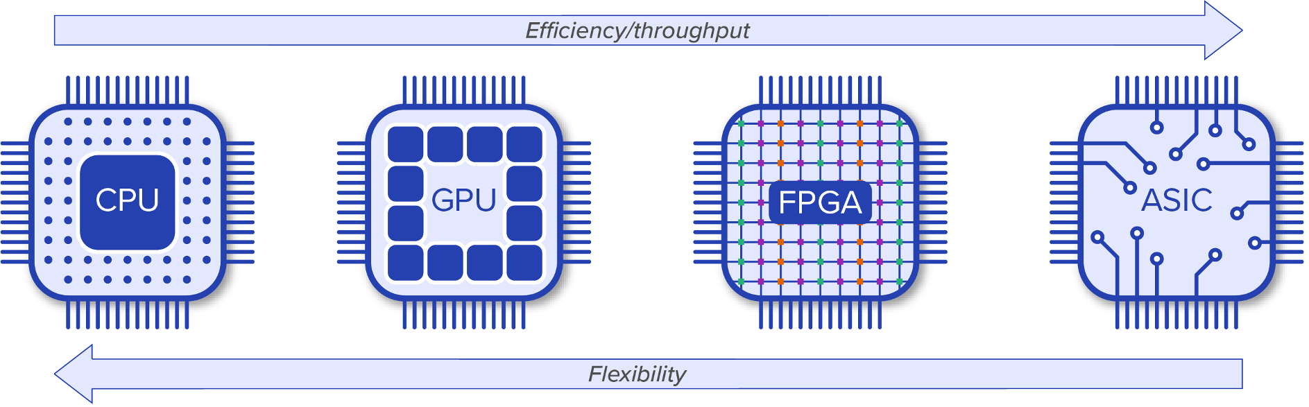
Many kinds of processing chips could be used to implement the DSP in an IoC device, so why has the FPGA emerged as the go-to chip? There are several common classes of chips capable of fast signal processing such as CPUs (Central Processing Units), GPUs (Graphical Processing Units), and ASICs (Application Specific Integrated Circuits). Each of these chips is the result of a different optimization. Figure 3 shows these chips arranged on a spectrum of increasing efficiency and decreasing flexibility. Starting from the left is a CPU, which is the king of flexibility and is the work horse of general-purpose computing. A CPU is probably working away inside the device you are reading these words on. Moving to the right we come to a GPU, which is less flexible but optimized for high-throughput parallel processing with many more cores (perhaps 100x more) than a typical CPU. As the name suggests, a GPU’s primary purpose was to perform calculations related to 3D computer graphics.
An FPGA is even more parallel with many thousands of operations happening simultaneously and independently across the chip. The FPGA chip does not have cores but instead has a web of distributed resources such as logic, multipliers and memory arranged across the chip. The connections between these resources are reconfigurable. The FPGA processing instructions are modified by rewiring the connections between the resources. But modifying instructions takes much longer than for a CPU, which is efficient at dealing with serialized instructions. Instead, FPGAs are optimized for serialized data with instructions that are changed very infrequently. I like to think about the FPGA’s resources like the stones in a shallow riverbed directing the water (the data) flowing across them. FPGAs are naturally suited to parallel processing as operations happen independently across separate sections of the FPGA fabric. Complex digital signal processing (DSP) chains can be efficiently implemented in parallel if pipelining techniques can be used. Different stages of the DSP can be performed simultaneously in separate sections of the FPGA by operating on the previous stage’s output at the last iteration (occurring once per clock period/cycle). In this way n stages of signal processing can be implemented by n independent regions of an FPGA with a high throughput of 1 output every clock cycle, but with a latency of n cycles. For clock cycles in the range of 2-10 nanoseconds, this latency usually is of negligible impact, even for closed-loop feedback control applications.
At the far right of Figure 3 we come to the least flexible but most efficient processor, an ASIC. Returning to the riverbed analogy, in the case of ASICs the stones have been concreted in place. An ASIC’s silicon can be highly optimized for the exact signal processing required, but then is fixed at the time of fabrication and cannot be changed over the life of the chip. The design and fabrication of a custom ASIC has high upfront costs, and so they tend to be cost effective only if large quantities are needed. IoC devices tend heavily towards efficiency, but some degree of flexibility is needed and so an FPGA – the penultimate chip in Figure 3, is favored.
Although the primary signal processing is typically implemented on an FPGA, a CPU is great for managing the network connection and configuration functions. For this reason, most IoC devices use a system on chip (SoC) solution where an FPGA and a processor are both present. This includes all systems from Liquid Instruments’ and Red Pitaya and some of Digilent’s newer higher end products. The rise of Artificial Intelligence applications is driving the development of new types of signal-processing chips. With the increase of “fabless” chip design houses, coupled with dedicated semiconductor foundries houses like TSMC, we are seeing a renaissance of silicon chip designs, and it will be interesting to see how IoC devices will benefit from these developments.
Reconfigurable Hardware Deserves a Reconfigurable User Interface
The user interaction with IoC devices is also different from that of standalone test equipment. In conventional test equipment “boxes” the user interface is a grid of front panel buttons with a built-in screen. IoC devices tend to not have front panel buttons because the controls required change depending on which instrument is running. One unexpected consequence is that most equipment then does not feature a built-in screen. If one needs a separate computing system for control, then this screen can also provide the entire user interface, often with superior usability.
By using readily available computers or tablets rather than custom built integrated screens, IoC users have broad choices. IoC devices tend to favor computer industry communications standards – ethernet, Wi-Fi and USB over the more niche test and measurement standards. You probably won’t be seeing RS232 or GPIB as the preferred way of talking to your IoC device.
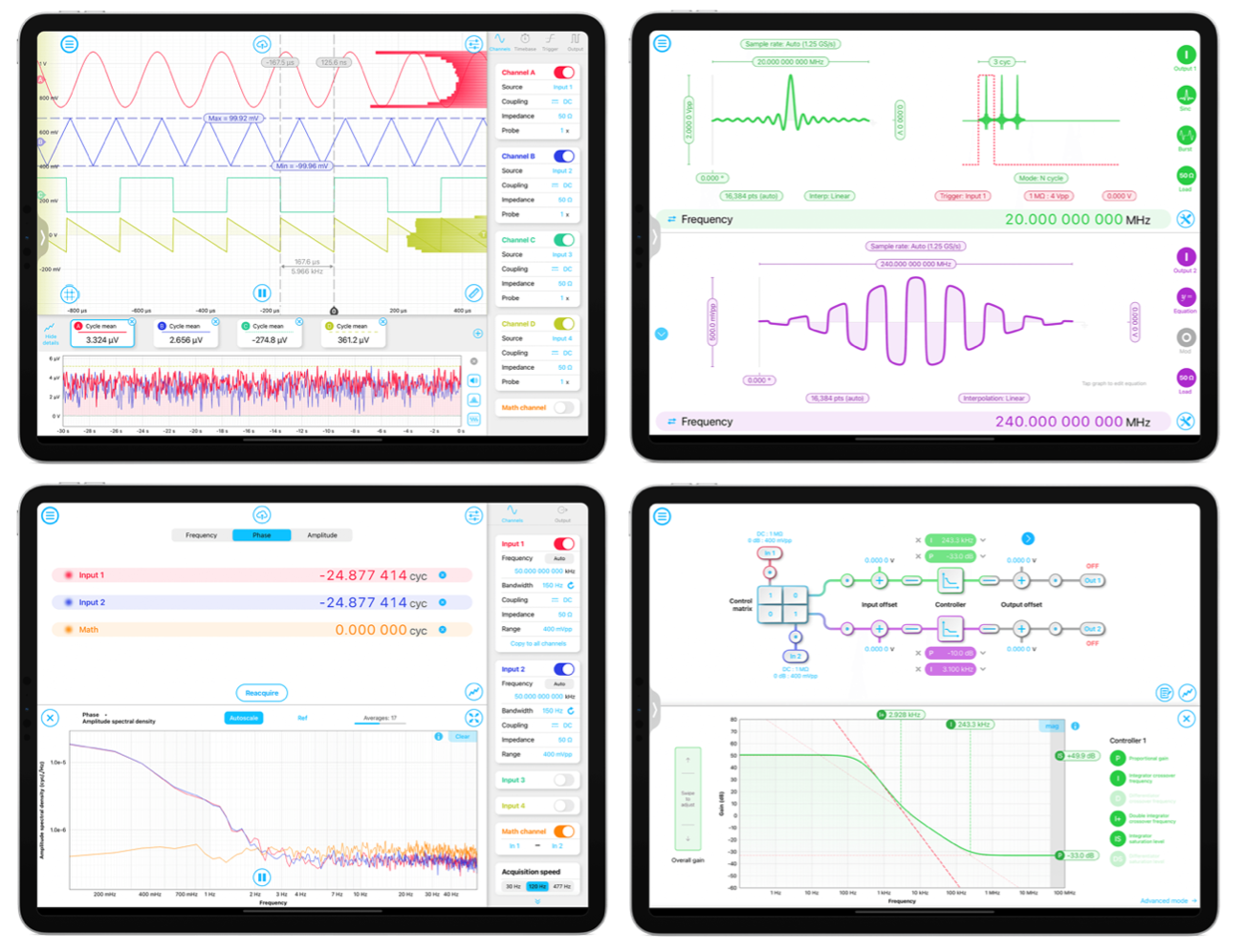
When Liquid Instruments launched Moku:Lab several years ago, we took the opportunity to rethink the entire user experience. We work a lot in large (optics) labs and wanted a UI decoupled from the hardware so that we could bring it with us as we move around the lab tweaking things. A tablet was a great form factor. Rather than port the conventional test equipment user interface to a tablet, we set out to bring the best of modern user interface design to test equipment.
Many benefits flowed from this decision. Training is reduced as many younger users have grown up on smart phones and instantly know how to use things. We’ve observed that a touch screen inspires a sense of exploration in new users, without the fear that they will “break something” that many felt with physical knobs and buttons. The interface is consistent across different instruments, making it easier to learn and remember how to use all instruments on the platform.
By using mainstream, modern operating systems there is automatic access to things like cloud storage (e.g., Dropbox, Google Drive etc.) without requiring users to sign up to a custom cloud storage service just for their test equipment. And finally, as we are users ourselves, we tried to make it fast, beautiful and generally just delightful to use.
The Future of IoC: What’s Next?
What we see today is just the beginning of IoC and things are changing fast, both in the underlying technology and the refinement of IoC devices as a platform. As the parallel processing resources of FPGAs continue to increase, we can add more features, improve specifications and build more capable instruments. The first wave of IoC devices replaced single stand-alone instruments like oscilloscopes or arbitrary waveform generators. With more powerful chips, Instrument-on-Chip devices will begin to supplant entire systems of test equipment. Instead of purchasing a PXI chassis and multiple hardware modules, systems such as Moku:Pro can be used that run multiple, hot-swappable software modules.
Some advantages are obvious. You are in the lab at 2am trying to get data for a deadline and you are missing a key piece of test equipment. You can now just download it and have it running in minutes, rather than ordering new hardware and waiting weeks for delivery. Other advantages are perhaps less obvious, but potentially more impactful. For example, in a PXI system, modules typically communicate either by connecting front panel inputs and outputs with cables or using the PXI back plane, sometimes through an intermediary processor using Direct Memory Access (DMA) channels. This transfer method has severe limitations on speed, latency and determinism of the data transfer between hardware modules. Alternatively, using cables to connect analog signals can degrade the signal-to-noise ratio (SNR) as signals are converted from digital to analog and back again. With multi-instrument capable IoC systems, signals can be passed between instruments without ever leaving the FPGA chip. This gives high data rates with ultra-low latency and no degradation of SNR. Some PXI hardware modules require an external clock/synchronization module costing thousands of dollars to sync their time base with other modules. Not so on an IoC device where all modules run on the same chip inside the same clock domain. From next month, Moku:Pro with multi-instrument capability can be configured to replace an entire test system. Of course, that test system configuration can be switched out with a different test configuration in a matter of seconds to now replace multiple test systems. We think that multi-instrument will be a game changer for people with complex test needs.
We are also excited about a second major functionality that will be released for Moku:Pro next month alongside multi-instrument: access for users to program the FPGA. This will allow expert users the ultimate in customization. Users will be able to perform everything from implementing simple custom measurements to building entirely new sophisticated instruments. Building an entire instrument is a complex task, and not for the faint of heart, but the FPGA in the Moku:Pro is big (it’s an Zynq UltraSCALE+ ZU9EG with more than 600,000 logic cells and 2,520 DSP slices!) so hopefully running out of resources won’t be a problem. Better yet, users’ custom FPGA creations will run in multi-instrument mode, which means that you can connect it up to our existing instruments to provide a user interface and save data with minimal hassle.
IoC: The Computer of Test Equipment
Computers have revolutionized so many aspects of modern life that it is hard to find applications where they are not the solution to processing needs. In the past, people used a typewriter for writing letters and a calculator for calculating things. Then along came the computer and changed everything. It can help us write letters and it can calculate things, but it can do a whole lot more that we never dreamed of at the time they were invented. Computers have not conquered test and measurement in the same ways that they have other industries, or at least do not provide the complete solution. We believe that with IoC we have discovered the recipe for the computer of the test and measurement industry.
Learn more about Liquid Instrument’s latest advancement in IOC technology, Moku:Pro.
Have questions or want a printable version?
Please contact us at support@liquidinstruments.com