This lab tutorial discusses a typical undergraduate electronics lab exercise and how it can be effectively conducted using Moku:Go to teach the fundamentals of an AM Radio receiver and Lock-in Amplifier.
Moku:Go
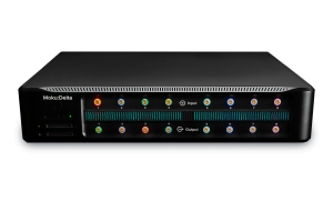
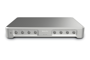
 Moku:Go combines 15+ lab instruments in one high performance device, with 2 analog inputs, 2 analog outputs, 16 digital I/O pins and optional integrated power supplies.
Introduction
The purpose of this lab is to introduce the basics of the AM radio receiver and demonstrate the basics of using a Lock-in Amplifier. You will be using the Lock-In Amplifier, Digital Filter Box, and Spectrum Analyzer instruments and the integrated power supply to design and optimize an AM radio receiver.
Amplitude modulated (AM) radio, while largely succeeded by frequency modulated (FM) radio, is still an incredibly useful method to transmit messages via radio waves. In this lab you will design and implement an AM radio receiver. You will learn to find the local AM radio frequency and implement a radio receiver using the Lock-In Amplifier. Figure 1 displays the AM radio signals picked up in Canberra, Australia using the Spectrum Analyzer instrument.

Figure 1. Example of the Spectrum Analyzer in the Canberra region
Background
AM Radio
In AM radio the amplitude of the signal is modulated; this is compared to FM radio where the frequency of the signal is modulated. This difference can be seen in Figure 2 where the amplitude of the wave is clearly varying in the AM modulated waveform, while in the FM modulated waveform the frequency of the sine wave varies with time. Both types of radio transmissions have advantages and disadvantages. Commercial AM radio stations operate in the 535 kHz – 1605 kHz range and thus typically have a longer range compared to FM in the 88 – 108 MHz range, however it is more susceptible to noise and is far more suited to talk radio compared to music-based radio shows.
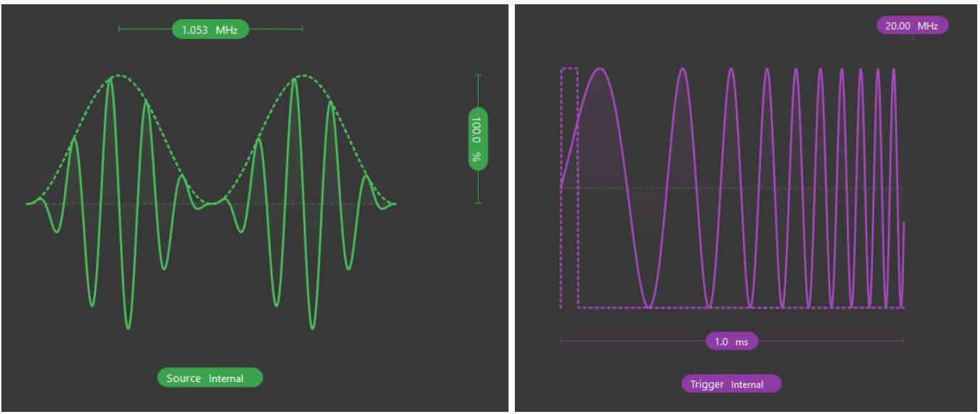
Figure 2. Example of an amplitude modulated waveform and a frequency modulated waveform using the Waveform Generator on Moku:Go.
AM radio operates by using a sinusoidal carrier wave which is modulated with the message signal (audio signal); this audio is the information that is being sent. In this type of modulation, the amplitude of the carrier wave is altered by the message signal (hence the term AM).
The modulated signal corresponding to a particular radio station can be clearly seen as a spike in the frequency domain (e.g. Figure 1), though it is usually hard to see in the time domain. The Moku:Go FIR Filter Builder helps by allowing us to set up a narrow bandpass filter around the radio station, removing almost all of the signal other than the station.
An example can be seen in Figure 3, where the FIR Filter Builder picks out an AM radio station at approximately 600 kHz. The AM carrier, modulated with the voice signal, can clearly be seen in the blue trace. The red trace (antenna input) shows that without a narrow bandpass, it’s impossible to pick this or any other radio station; in fact, the signal is completely dominated by the ~25 kHz switching of the dimmable LED lighting in the office where the screenshot was taken.
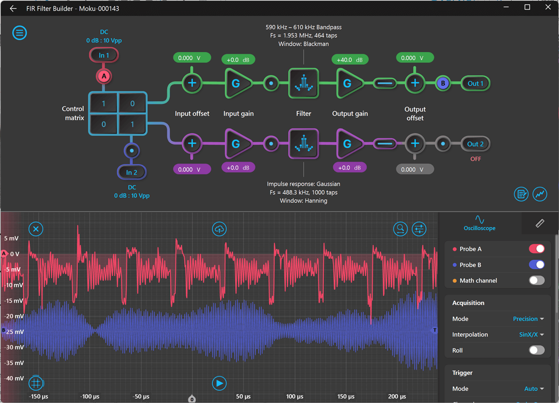
Figure 3. FIR Filter Builder isolating an AM radio station (blue trace) from the background signal (red).
To receive and then listen to the message signal, a radio receiver is required to receive the specific AM radio frequency and demodulate it to separate out the carrier signal from the message signal. The block diagram for a simple AM radio receiver is shown in Figure 4.
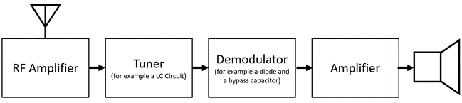
Figure 4. Block diagram of the AM radio receiver
A receiver operates by using a radio antenna to detect radio waves; however, this signal is usually relatively weak, therefore an RF amplifier is required to boost the signal so it can be further processed. As the antenna will capture all possible frequencies, a tuner is required to find the specific frequency needed.
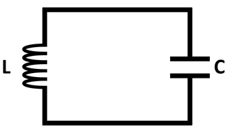
Figure 5. Example schematic of the LC circuit
Analog Demodulation
The analog demodulation tuner typically consists of an LC (Inductor-Capacitor) circuit, which can be seen in Figure 5. Depending on the inductor and capacitor used, the circuit will resonate at a specific frequency. All other frequencies above and below this resonant frequency will be blocked. The message signal can be rectified to only give a DC signal and demodulated from the carrier wave via a diode and bypass capacitor. The message single can then be amplified and sent to speakers, headphones, etc.
Lock-in Amplifier
A lock-in amplifier is a powerful device that can separate out the modulated signal from a noisy background, in our case, a specific AM signal from an array of signals. This means that the lock-in amplifier can function as a radio receiver since it contains several key components from a radio receiver.
The Moku:Go Lock-in Amplifier is able to demodulate a modulated signal, for example a radio wave, by using a phase-sensitive detector (PSD). It uses a sinusoidal reference signal with the same frequency as the carrier signal. It can track any variances from the reference signal and hence able to track frequency drift.
The PSD multiplies or “mixes” the two signals together, generating sum and difference terms of the two signals. The required frequency and reference signal consist of the same frequency and hence the difference between the frequencies is zero. Therefore, the required radio wave signal is set to DC.
The mixed signal is then sent through a lowpass filter which removes the AC components of the modulated signal. This leaves only the DC signal that is proportional to the signal amplitude, here the signal can then be amplified using a DC amplifier.
The output amplitude can be found from the signals sent through the mixer and lowpass filter. These can be found in either rectangular or polar coordinates. The amplitude R can be found from converting between the coordinates. For AM signals, only the amplitude or R is required (in polar coordinates); the phase of the signal can be ignored.
Pre-lab Exercises
- Find and detail the list of AM stations currently in your area.
- What signal do you think will be the strongest? Why?
Experimental Setup
Components
- Moku:Go [2x]
- Antenna
- Speaker
- Low Noise Amplifier (optional)[1]
- Alligator clips
Lab Procedure
Part 1
- Ensure you have the latest version of the Moku: desktop app[2] downloaded on your computer.
- Plug in the magnetic power adapter to each Moku:Go and wait for the front LED to turn green.
- These first steps will address the configuration of Moku:Go #1.
- Connect the antenna to the Moku:Go Input 1 as shown in Figure 6 and Figure 7.
[1]Commonly available 30 dB LNA. For a full bill of materials, please contact support@liquidinstruments.com
[2]Moku:Go can be connected to your laptop in three different ways: ethernet, USB-C, and Wi-Fi. Please refer to the Moku:Go Quick Start Guide on how to connect your Moku:Go to your computer. Once connected, Moku:Go will show up in the device select screen of the Windows or MacOS application.
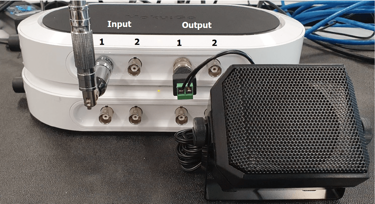
Figure 6. Photo of Part 1 Moku:Go Set up
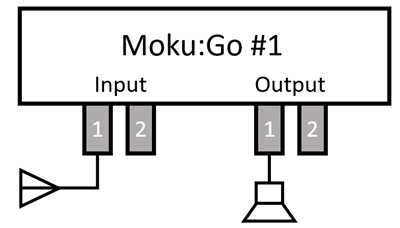
Figure 7. Block diagram of Moku:Go set up part 1
- Double click on the Spectrum Analyzer. Find the AM range and feel free to average the spectrum to improve the graph.
- Find the most dominate AM radio signal frequency, you can do this by adding a tracking cursor. The signals should be in the range of less than 2 MHz.
- An example of the Spectrum Analyzer and the settings configuration can be seen in Figure 8.
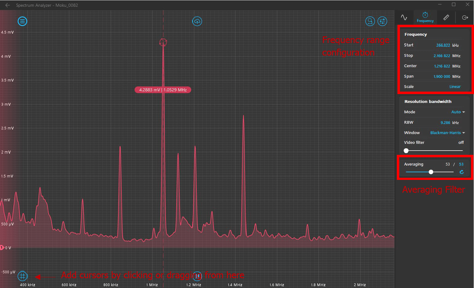
Figure 8. How to configure the Spectrum Analyzer
5. Connect your speaker to Output 1 of Moku:Go #1.
- Return to the instrument selection screen and double click on the Lock-in Amplifier. Open the oscilloscope section to ensure you can see both A and B.
- Add Probe A to Input 1 (the antenna)
- Add Probe B to Output 1 (speaker)
- An example of the Lock-In Amplifier instrument page can be viewed in Figure 9.
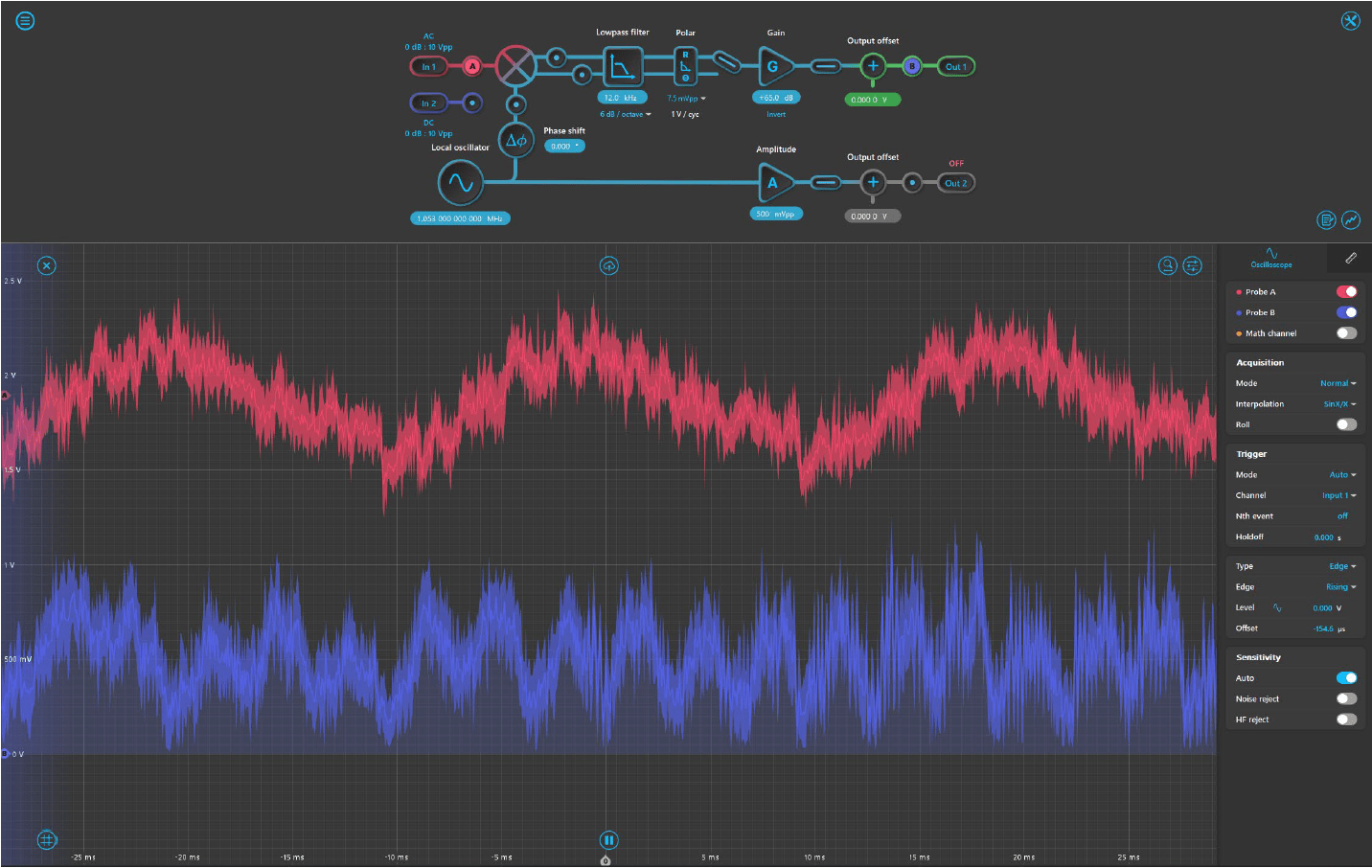
Figure 9. Example of Lock-in Amplifier demodulating an AM radio station. The upper (red) trace is the antenna signal, lower (blue) trace is the audio.
6. Change the local oscillator to the frequency of your most dominate AM signal. Set the lowpass filter to 12 kHz to begin with. Change to polar and alter gain as required. You may need to alter the lowpass filter and gain to improve the signal and produce the clearest sound possible. Be careful not to saturate the signal. An example set up of the various variables for the local Canberra region is given in Figure 10.
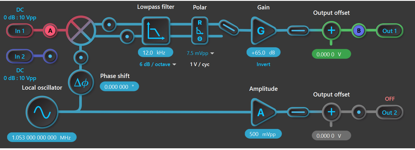
Figure 10. Example of Lock-In Amplifier with settings for the Canberra region.
Part 2
Move the speaker connection cable to output 2 of Moku:Go #2. Attach a cable from output 1 of the Moku:Go #1 to the input 2 of Moku:Go #2. This set up can be seen in Figure 11 and Figure 12.

Figure 11. Photo of Moku:Go set up part 2
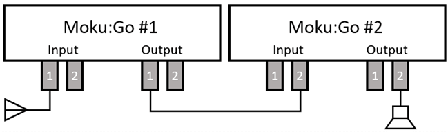
Figure 12. Block diagram of Moku:Go set up part 2
2. Return to the main screen and double click the icon for Moku:Go #2. Double click on the Digital Filter Box. The Digital Filter Box interface can be seen in Figure 13.
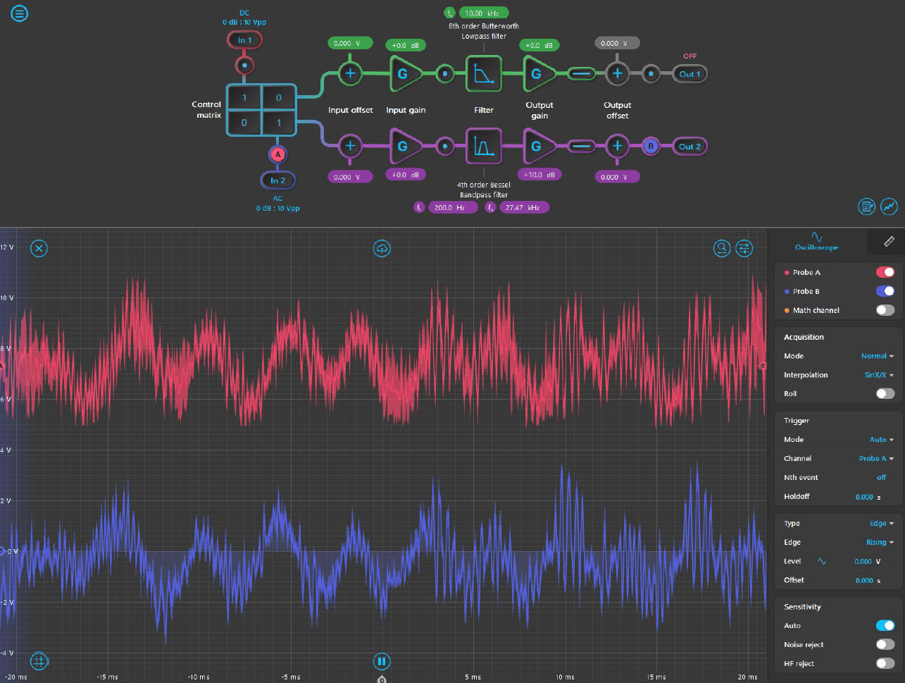
Figure 13. Digital Filter Box user interface
3. Add probe A to input 2 and probe B to output 2. To begin with, change your filter to the Bessel bandpass filter and alter gain as required. Alter the frequencies to isolate just the message signal, i.e. the music or the voices and thus try to remove the low frequency noise. Try to aim for frequencies that are produced from music and voices. Figure 14 gives the Digital Filter Box variables for the Canberra Region.
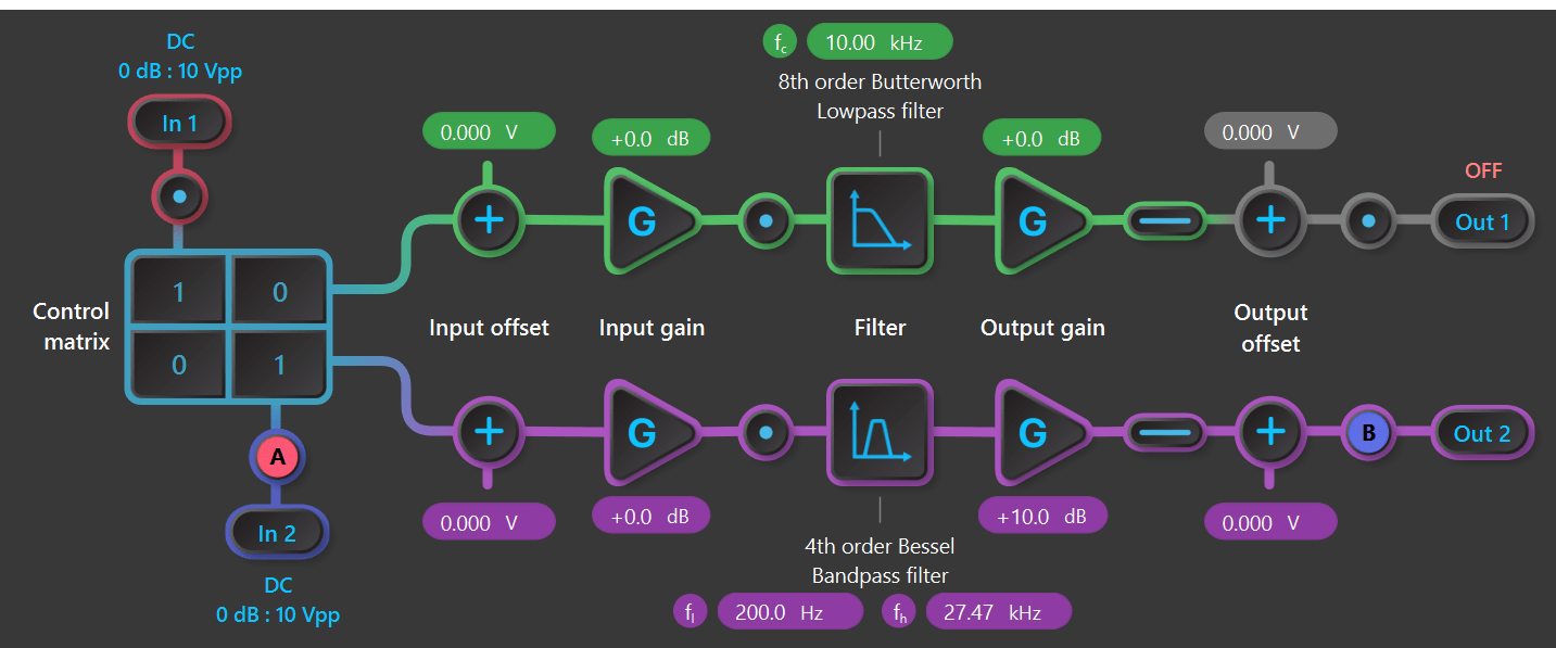
Figure 14. Example of the Digital Filter Box for the Canberra region
Part 3 (optional)
1. Connect the low noise amplifier between the antenna and the input 1 of Moku:Go #1. To power the low noise amplifier, connect the alligator clips to the power connection and to the back of Moku:Go #1. The set up can be seen in Figure 15.
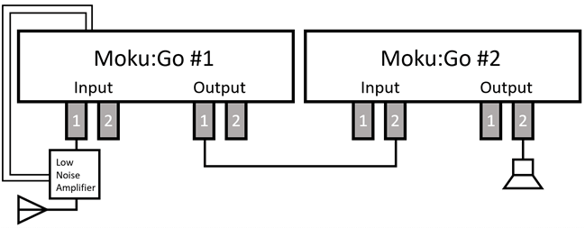
Figure 15. Block diagram for Moku:Go set up part 3
2. Ensure that it’s connected to the PPSU2, or a similar 12 V power supply. Click on the menu button to open up the power supply and set to a voltage of 12 V. A possible power supply pop window could look like Figure 16.
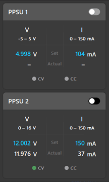
Figure 16. Example of the PPSU
3. Change the variables of the Digital Filter Box and Lock-in Amplifier as necessary to produce the clearest signal possible.
4. Try and change in other AM signals in your area, can you optimize your sound quality by changing the variables in the Lock-in Amplifier and Digital Filter Box?
Summary
This lab explores the use of a lock-in amplifier as an AM radio receiver on Moku:Go. The lock-in amplifier is a powerful tool for students to discover how to demodulate signals from noisy backgrounds. Additionally, the students are able to learn how to further improve signal clarity with a number of other tools.
Publishing and reporting of the results are easily done with screen capture or file sharing within the Moku: App. You can do this by clicking the cloud icon at the top of your screen.