


Precise and sensitive phase detections are often required for impedance and optics-based measurements. For example, measuring the phase shift between current and voltage reveals the complex impedance of a device or component. Very small displacements can be measured by the phase shift between control and measurement arms from an optical interferometer. Liquid Instruments’ reconfigurable Moku platform provide two instruments that detect the phase of a radio frequency signal, the Lock-in Amplifier and the Phasemeter. In this application note, we will introduce the working principles of these instruments and provide an instrument selection guide for different measurement scenarios. For more information, read our ebook: Measuring phase with precision: a guide to phase measurement methodologies.
Introduction
The Lock-in Amplifier and Phasemeter are two commonly used instruments to retrieve phase information from oscillating signals. A lock-in amplifier can be considered an open-loop phase detector. The phase is calculated directly from a local oscillator, mixer, and low-pass filter. The Phasemeter implements a digital phase-locked loop (PLL) as its phase detector. A feedback signal is used to update the frequency of the local oscillator. It can be considered a closed-loop approach.
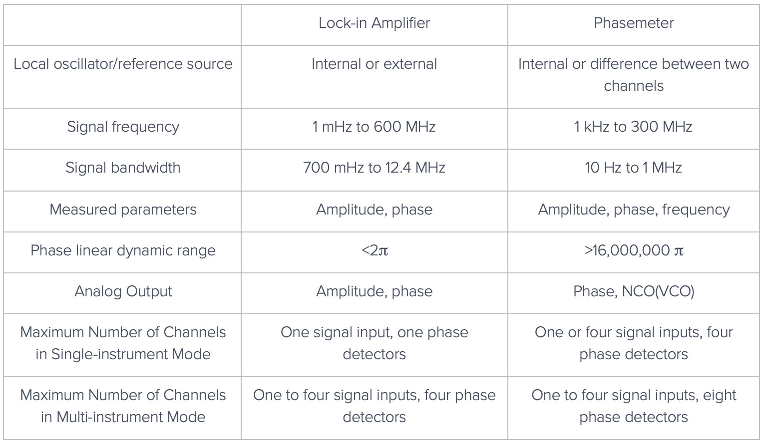
Before we examine each of the instruments, here is a quick summary that highlights the difference between the Lock-in Amplifier and the Phasemeter (for phase detections). Please note that the specifications used in this table are based on Moku:Pro.
Principle of Operation
Principle of lock-in amplifier
There are three key components of a lock-in amplifier: a local oscillator, a mixer, and a lowpass filter, as shown in Figure 1.
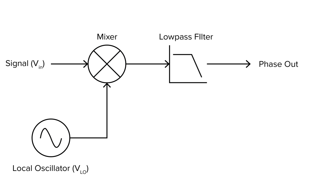
The input signal Vin and the local oscillator VLO can be described by a sine and a cosine function:
\(V_{in} = A_1 \times \sin(\omega_{in} t + \Delta\phi)\ \)
\(V_{LO} = A_2 \times \cos(\omega_{LO} t)\ \)
A1 and A2 represent the amplitude of the oscillators. ωin and ωLO represent the frequencies of the input and local oscillator. ∆ϕ denotes the phase angle difference between the input signal and local oscillator. The output of the mixer Vmixer is the product of the input and local oscillator.
\(V_{mixer} = A_1 \times \sin(\omega_{in} t + \Delta\phi) \times A_2 \times \cos(\omega_{LO} t)\)
Applying the trigonometric identities
\(\sin(\theta) \cos(\varphi) = \frac{1}{2}[\sin(\theta + \varphi) + \sin(\theta – \varphi)]\)
Assuming ωLO ≅ ωin= ω, Vmixer can be written as
\(V_{mixer} = \frac{A_1 A_2}{2}[\sin(2 \times 2\omega t + \Delta\phi) + \sin(\Delta\phi)]\)
The lowpass filter filters out the higher frequency component sin(2×2ωt+∆ϕ). Assuming the amplitude of the input signal and local oscillator is fixed, the output signal Vout can be expressed as
\(V_{out} \propto \sin(\Delta\phi)\)
There are a few things to note here: the output from a single-phase lock-in amplifier is proportional to sin(∆ϕ) instead of ∆ϕ. This significantly limits the linear dynamic range for phase detection as the sine function is a periodic function, and it only provides a (nearly) linear response for a very small range. Also, any fluctuation of the amplitude may induce some systematic errors. Liquid Instruments Lock-in Amplifiers provides the option for dual-phase demodulation, which effectively separates the influence from amplitude and phase on the output. A more detailed explanation of the dual-phase demodulation can be found in this video. Nevertheless, the linear dynamics range remains limited at 2π. On the other hand, the digital signal processing (DSP) for the Lock-in Amplifier is much simpler than the Phasemeter. This allows the Lock-in Amplifier to process data at a higher rate, which provides wider demodulation bandwidth. It also allows users to feed in a local oscillator (reference) directly from an external device for directly measuring the relative phase difference between two oscillators. The open-loop nature of the lock-in amplifier ensures the instrument provides a valid, instantaneous response that is less vulnerable to sudden signal loss or abnormality. It can be used to measure signals near or at the input noise floor.
Principle of Phasemeter/PLL
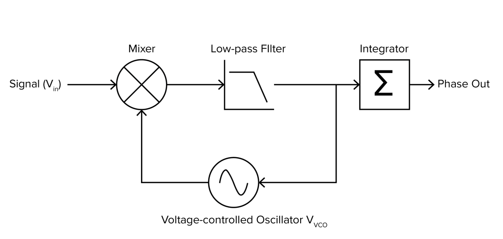
The core phase detection unit in the Phasemeter is a phase-locked loop (PLL). The basic measurement principle of the Phasemeter is to lock an internal oscillator to the input signal. The phase of the input is then inferred from the known phase of the internal oscillator. The PLL is shown in Figure 2. At first glance, it is very similar to a lock-in amplifier. However, there are two important differences: 1) the local oscillator is replaced by a voltage-controlled oscillator (VCO) and 2) the output of the lowpass filter is fed back to form a closed loop.
The output of the VCO VVCO can be expressed as
\(V_{VCO} = A_{VCO} \cos(\omega_{set} + K \cdot V_{VCOinput})t)\)
ωset is the set/center frequency of the VCO. K is the sensitivity of the VCO. VVCOinput is the input of the VCO. AVCO is the amplitude of the VCO. Both K and AVCO remain constant during normal operation. Without getting into details about closed-loop control theory, this configuration tries to maintain a zero instantaneous frequency difference between the input signal Vin and VVCO. Therefore,
\(\omega_{in} = \omega_{set} + K \cdot V_{VCOinput}\)
As both ωset and K are known based on the instrument settings, the frequency of the input can be calculated based on the VVCOinput. In the meanwhile, the accumulated phase of the reference at ωset at time t can be denoted as
\(\phi_{set}(t) = \int_{-\infty}^{t} \omega_{set}(\tau)d\tau\)
The accumulated phase of the input signal can be approximated by the ϕvco. Here we define the K∙Vvcoinput term as ωdiff.
\(\phi_{vco}(t) = \int_{-\infty}^{t} \omega_{set}(\tau)d\tau + \int_{-\infty}^{t} \omega_{diff}(\tau)d\tau\)
Therefore, the accumulated phase difference between the input signal and reference (oscillator at the set frequency) can be retrieved by the integrated frequency difference/error signal from the loop.
\(\Delta\phi(t) = \phi_{vco}(t) – \phi_{set}(t) = \int_{-\infty}^{t} \omega_{diff}(\tau)d\tau\)
This approach provides a native phase unwrap support for phase detection. The output is linearly related to the phase difference. The instantaneous frequency of the input signal is also measured via Vin. Additionally the Phasemeter has a built-in secondary oscillator to calculate the amplitude of the input signal, similar to a dual-phase lock-in amplifier. Besides the phase from the out-of-loop integrator, the output of the Phasemeter can be set to generate a sinusoidal phase-locked copy of the input signal directly from the Numerically Controlled Oscillator (NCO; it can be considered as a digital counterpart of a VCO) with arbitrary amplitude and phase adjustment. On the flip side, a stable lock between the input and the NCO is always required for the PLL to function correctly. Any large discontinuation of the input may interrupt the measurement. For this reason, the lower carrier frequency boundary is more limited than the Lock-in Amplifier, as it is more challenging for the PLL to maintain a stable lock at very low frequencies. It is not recommended for measuring signals near the input noise floor.
Practical considerations and demos
In this section, we will discuss a few practical considerations when choosing between the Lock-in Amplifier and Phasemeter with demonstrations.
Linear dynamic range for phase detection
One of the key differentiators between the Lock-in Amplifier and Phasemeter is the linear dynamic range for phase detection. A single-phase lock-in amplifier has a phase linear dynamic range that is smaller than π. A dual-phase lock-in amplifier pushes the limit to 2π. In theory, the Phasemeter can track an unlimited phase change. In practice, the actual detection range is limited by the length of the number of digital bits used to represent the phase, which is about 16,000,000π on the Moku:Pro.
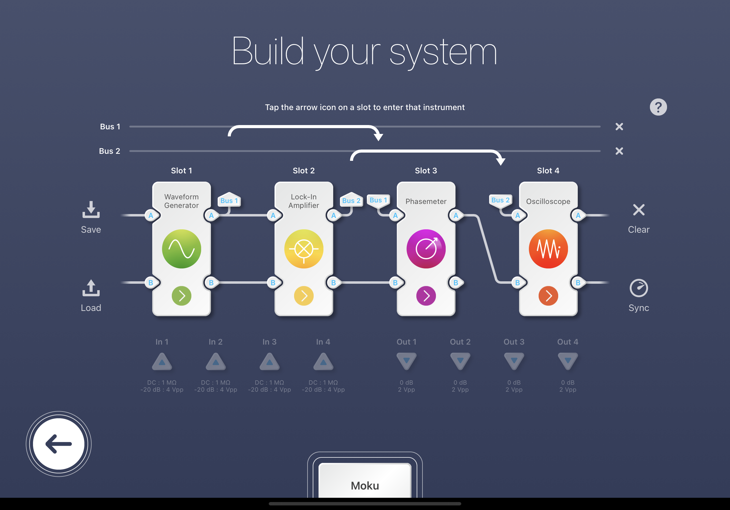
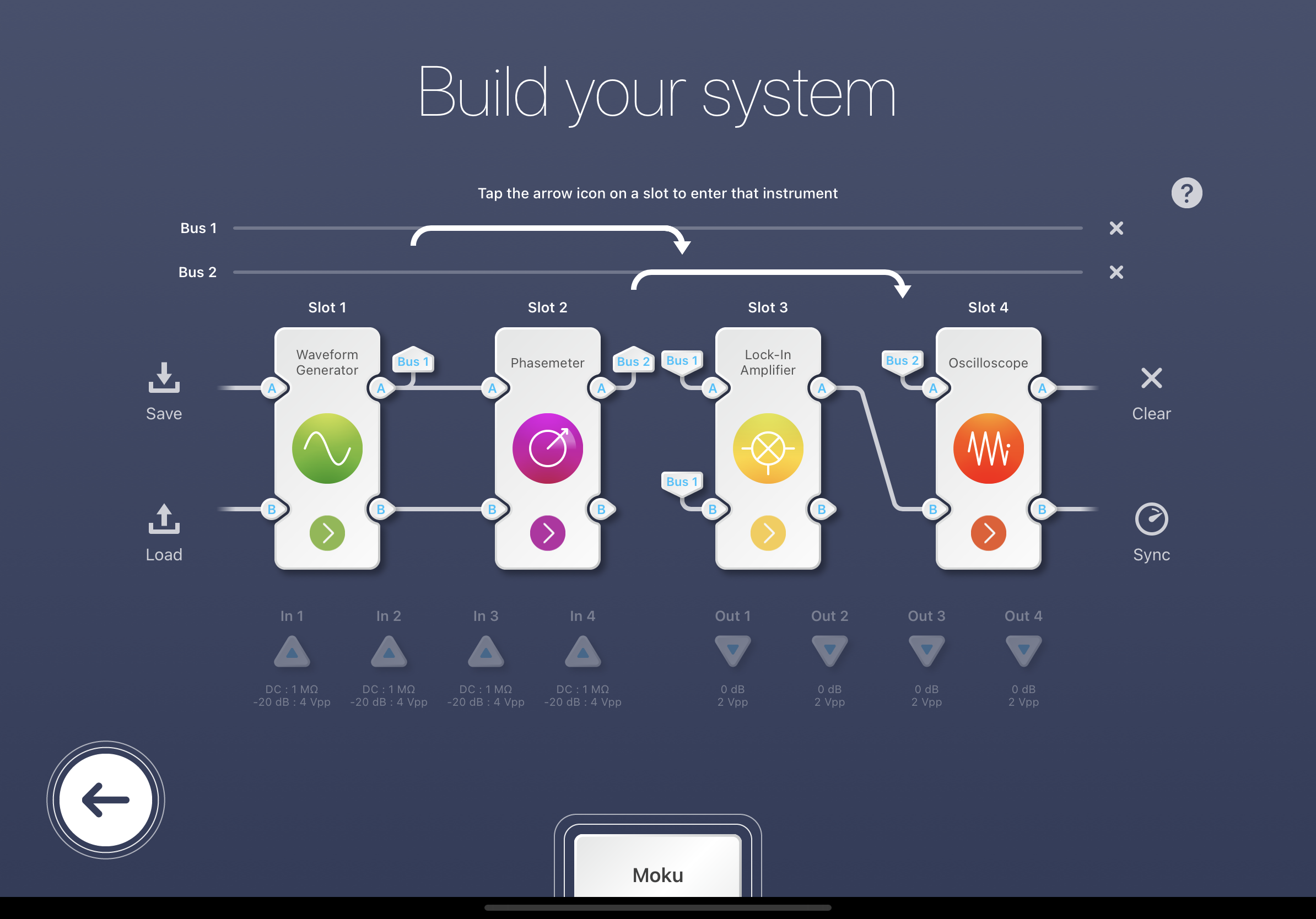
In this demonstration, a phase-modulated 10 MHz signal was input into Moku:Pro’s Lock-in Amplifiers in single and dual-phase mode and Phasemeter on via Multi-Instrument Mode (MIM). A more detailed explanation on MIM can be found here. The outputs from the phase detectors were logged by the Oscilloscope.
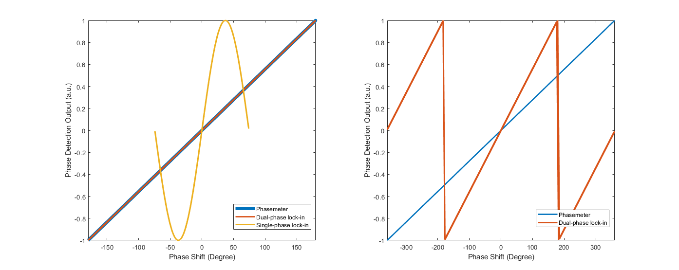
The normalized phase outputs (as analog signals) are plotted as a function of the phase shift in Figure 4. From Figure 4(a), both the Phasemeter and Lock-in Amplifier in the dual-phase demodulation mode provided linear phase responses within 360°. The Lock-in Amplifier in single-phase mode only delivered a near-linear response within 90°. The dual-phase demodulator wrapped the phase at ±180° while the PLL continuously output the phase linearly over the entire 720° phase shift range (Figure 4(b)).
Another major advantage of the Phasemeter compared to the Lock-in Amplifier is the phase error signal can be unwrapped and accumulated inside the PLL. This enables a closed loop to be lockable even if a slow actuator is used in a noisy system. A lock-in amplifier may wrap the phase error signal before a slow actuator reacts to the input.
Measurement with an unstable reference
The Lock-in Amplifier allow users to directly input a reference signal as the local oscillator. For applications in which the relative phase shift between two oscillating signals is measured, the lock-in amplifier provides a straightforward way to retrieve this information. The operation of Phasemeter requires an onboard oscillator as the absolute frequency reference. In this demonstration, a frequency modulated (FM) signal was fed into Lock-in Amplifier as the signal and reference, and the Phasemeter as the signal, as shown in Figure 5(a). The FM-induced phase fluctuation was only observed on the Phasemeter (red) on Figure 5(b). The output from the Lock-in Amplifier remained constant (blue).
(a)
(b)
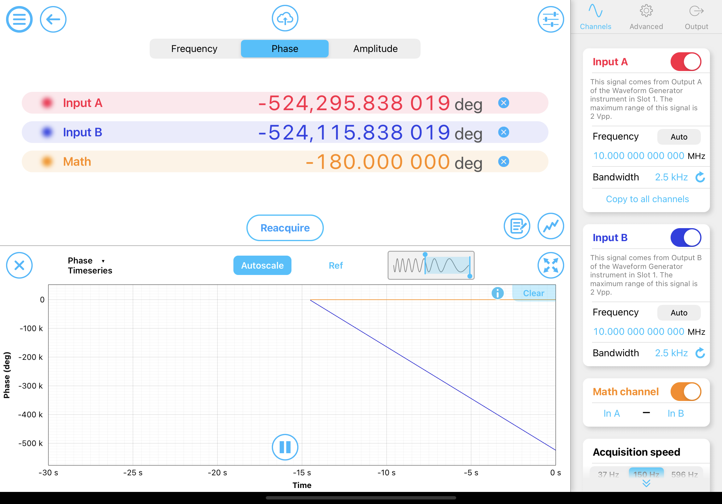
There are two ways to measure the relative phase difference between two oscillators with the Phasemeter. 1) The phase difference between two input signals can be calculated by ∆ϕ1-∆ϕ2, where ∆ϕ1,2 represents the phase difference between inputs to a common reference. To illustrate this effect, a pair of phase-locked sine waves with a 180° phase shift was sent to the Phasemeter. The built-in data viewer was used to log ∆ϕ1 (red), ∆ϕ2 (blue), and the ∆ϕ1-∆ϕ2 (orange), as shown in Figure 6. Although constant phase drifts were observed on both input channels, the math channel provided the correct phase difference between the inputs.
2) The master clock of Moku:Lab and Moku:Pro can be synchronized via a 10 MHz reference signal. If the reference oscillator can be synchronized with the 10 MHz, this allows the NCO on the Moku:Pro to have the same time base as the reference. However, the time base synchronization does not capture any parameter adjustment of the reference NCO (i.e., the reference source is purposely frequency modulated). Also, the PLL that is used to capture the 10 MHz reference may induce additional noise into the system. This method is not recommended unless the real-time difference is required to be output via an analog channel.
Measuring signals near the noise floor
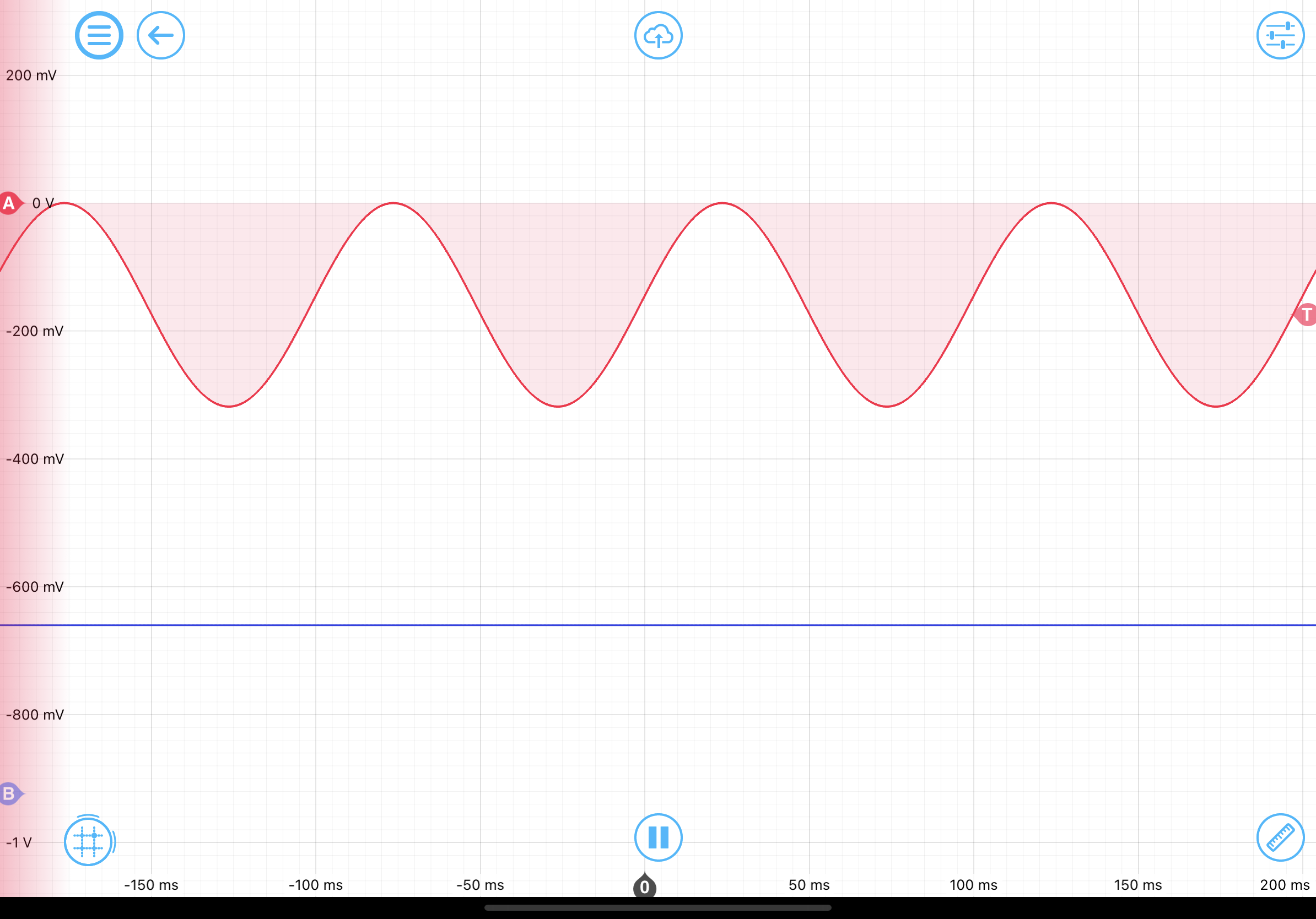
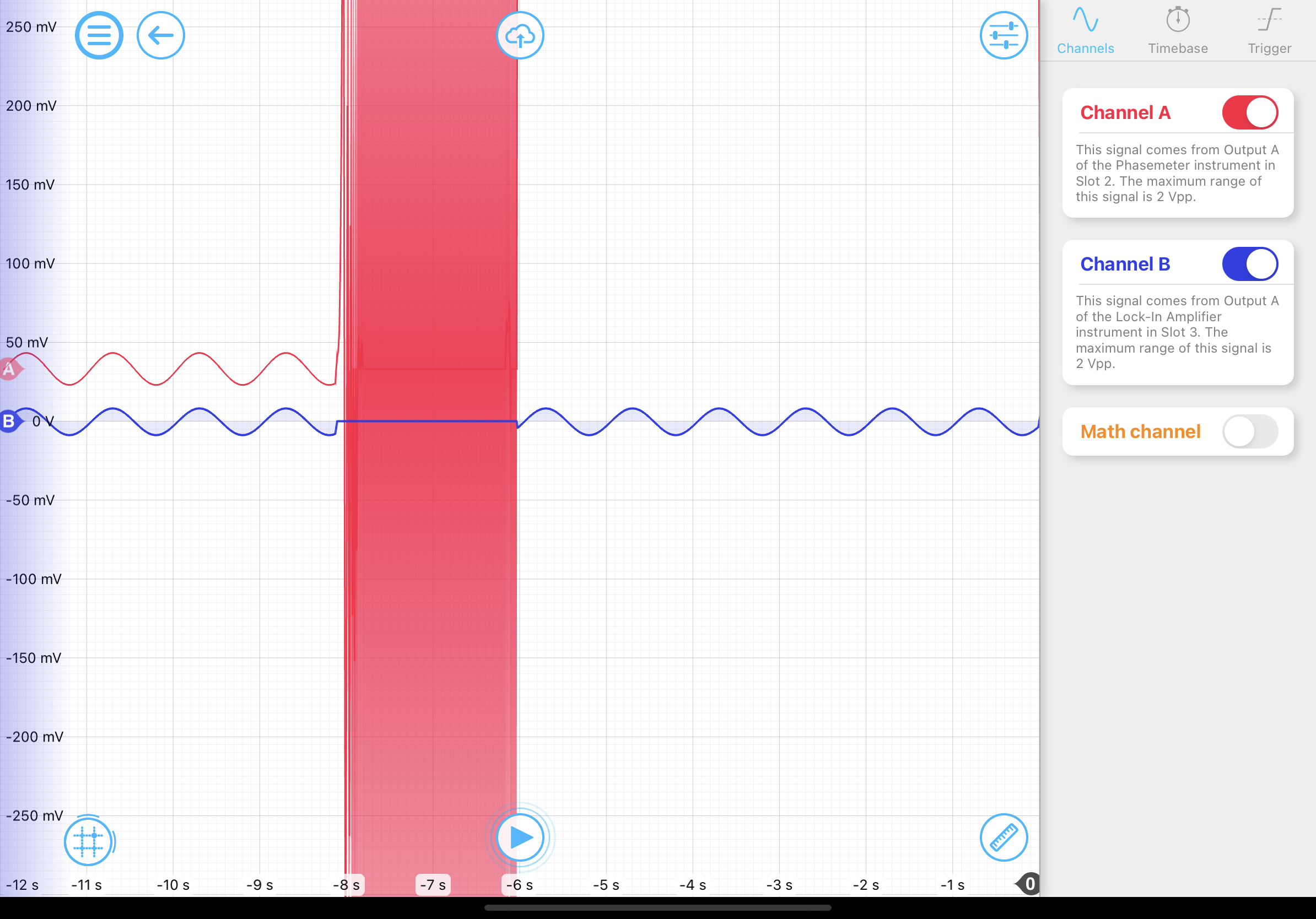
The Phasemeter requires a stable lock between the input signal and the local oscillator. There are several safety mechanisms built-in to prevent unexpected changes. For example, the “freewheeling” option automatically holds the loop at the last known state when the lock is lost. On the other hand, a lock-in amplifier’s output is always deterministic at any given time. To demonstrate this effect, a sinusoidally phase-modulated signal was sent to both the Lock-in Amplifier and the Phasemeter. Then, the input signal was turned off for about two seconds and turned back on. The outputs from both phase detectors were recorded on the Oscilloscope. From Figure 7, the output of the Phasemeter (red) drifted dramatically after the signal was reconnected. The output from the Lock-in Amplifier (blue) remained at 0 when the signal was disconnected and immediately returned to the expected value afterward.
Conclusion
Liquid Instruments’ Moku:Lab and Moku:Pro provide two software-defined instruments for sensitive phase detection: the Phasemeter and the Lock-in Amplifier. The closed-loop approach on the Phasemeter provides exceptional linear dynamic range while providing frequency, phase, and amplitude information of the input simultaneously. The Lock-in Amplifier is simple, fast, and predictable at all times. With Multi-Instrument Mode, these instruments can be deployed in parallel on a single FPGA chip. Up to eight PLL-based phase detectors can be deployed across the four input channels. Moku:Pro is an ideal solution for multi-channel phase detection and phase-locked loop applications.
References
[1] Shaddock, D., Ware, B., Halverson, P. G., Spero, R. E., & Klipstein, B. (2006, November). Overview of the LISA Phasemeter. In AIP conference proceedings (Vol. 873, No. 1, pp. 654-660). American Institute of Physics.
[2] Roberts, L. E. (2016). Internally sensed optical phased arrays.
Have questions or want a printable version?
Please contact us at support@liquidinstruments.com