


Introduction
Optical ring cavities allow researchers to filter incoming light by transmitting only the selected modes. This technique is useful when applications such as optical interferometry and spectroscopy require thoroughly conditioned laser beams. Researchers often choose the lowest-order mode — Gaussian mode — as the objective so the resulting beam has a Gaussian profile. Successful alignment into an optical ring cavity requires precisely setting the position and size of the beam waist, as well as the horizontal and vertical positions and tilt angles of the beam, with respect to the incident interface, a mirror, of the cavity.
Floquet, a joint venture between Australian National University spinout Aqacia and quantum computing services provider 2pi Software, has developed the Deep Learning Optimiser (DLO), a machine learning system designed for optimizing quantum and other complex systems. Typically, such systems are costly to sample because of limited time or resources, and are of higher dimensionality than the ring cavity alignment challenge. The group leveraged the DLO’s cloud-based nature to integrate it with Moku:Go, an FPGA-based test and measurement device from Liquid Instruments (Figure 1).
The Moku devices integrate multiple software-defined instruments in one piece of hardware, delivering the versatility required to seamlessly and automatically align an optical ring cavity. Moku devices are especially ideal for this task due to their API-enabled automatability. In this application, the portability and small form factor of Moku:Go delivered additional advantages for fast, flexible performance.

Figure 1: Moku:Go on the optical table using the digital input/output port to control other subsystems in the experiment.
The DLO uses a neural network ensemble and heuristic engine to cycle through a series of training and prediction sequences. This approach helps to establish a suitable control profile for a target system more quickly and accurately than currently possible with traditional human-based mechanisms.
Establishing proper control settings for both the laboratory and industrial equipment is critical to ensuring the equipment’s ability to consistently function as intended. The DLO and Moku:Go work together to enable this functionality in a highly automated manner, particularly in cases where:
- The target system operates restrictively under a sparse sampling constraint.
- It is monetarily expensive to acquire sample data.
- The problem domain is of high dimensionality.
- The target system operates in a cyclical manner and would benefit from automation.
- Hard parameter bounds exist, precluding many traditional learning algorithms.
The challenge
Traditionally, manual intervention is required to align a laser beam to an optical cavity. Rough alignment can be achieved by placing a detector in the path of the beam reflected off the input window of the cavity. While observing the detected spectrum, the scientist would then need to adjust the position and tilt of the incoming beam with a pair of mode matching mirrors, adjust the beam waist size, and optimize the position with a pair of lenses. This process continues until the absorption dips on the detector signal are observed. When the scientist is confident that some light is entering the cavity, they would then place the detector after the output window of the cavity, where it can detect light that has transmitted through the cavity. Finally, they would adjust the mirrors and lenses until the transmission spectrum forms a single peak at the desired mode.
The cavity alignment process is lengthy, and for complex experiments involving several optical paths, it must be repeated for each cavity. Additionally, the alignment will periodically require adjustments due to drift sources such as temperature fluctuations and mechanical perturbations. The DLO could readily optimize over the six-dimensional state space posed by this problem. However, a control layer is required to translate the DLO’s software outputs into physical adjustments (Figure 2).
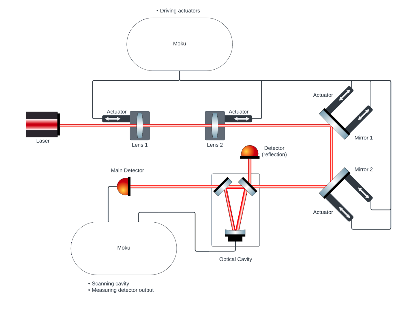
Figure 2: The optical setup including two Moku:Go devices, the laser source, and other optical components.
The solution
Using the Moku:Go Logic Analyzer as the driver for the actuators attached to the steering mirrors and the Oscilloscope for scanning the cavity and recording the detector signal, Floquet has successfully automated the alignment of a laser to an optical cavity. The Logic Analyzer takes a predicted setting from the DLO and generates pulse trains to drive the actuators to their new positions. The Oscilloscope then takes a measurement of the detector signal for analysis by the DLO. This cycle repeats until the cavity has achieved maximum quality alignment.
The result
Floquet integrated the DLO with Moku:Go, enabling the automatic alignment of a laser beam to an optical cavity. As long as the target mode can be seen and identified in the initial, manual alignment, the system is capable of taking over the alignment by finding and maintaining a high-quality alignment. The automated, DLO-driven system was able to definitively outperform expert human operators in alignment speed for comparable or better alignment quality. Figure 3 shows the measured cost function (intensity at the photodetector) vs. increasing run number. The shaded region highlights the initial sampling, a brief plateau from runs 0 through 25. By 600 runs, the DLO had optimized the optical cavity alignment to within the limit imposed by the ellipticity of the beam, with some optimal alignments occurring in as few as 300 runs.
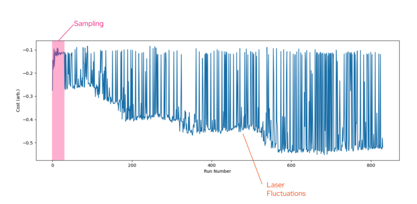
Figure 3: Measured cost function vs. run number results.
Figure 4 shows snapshots of the photodetector output, with a DC offset for visibility, for random mirror and lens configurations during the optimization process. The figure on the right shows the spectrum in the final configuration determined by the DLO. As desired, almost all of the optical power has been transferred to the Gaussian mode.
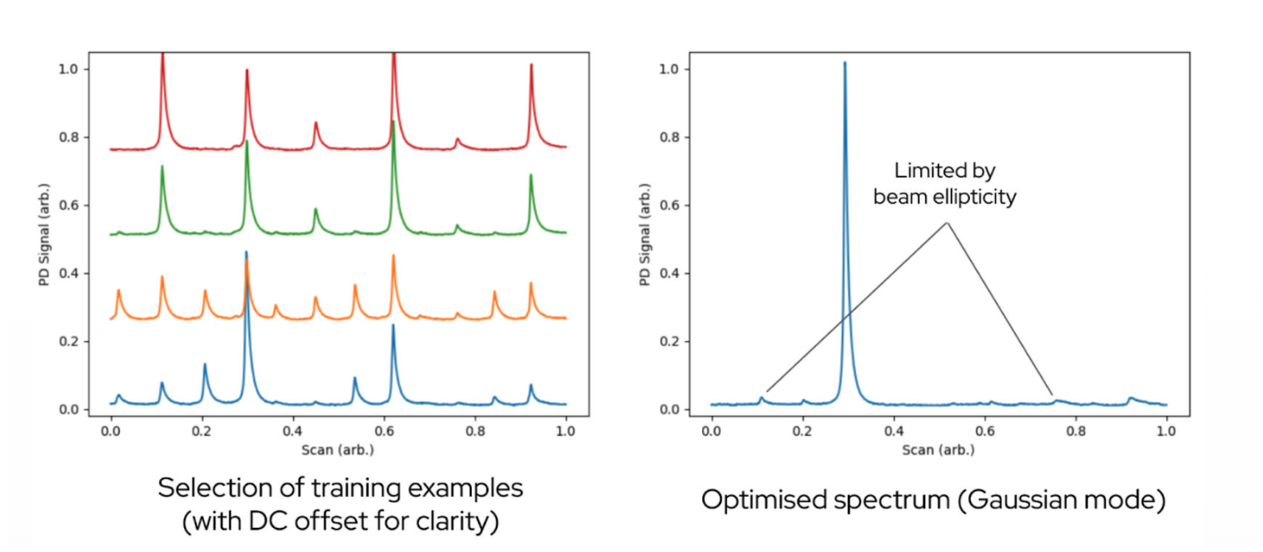
Figure 4: Photodetector output in training examples (left) and the optimized spectrum (right).
By integrating Moku:Go with the DLO, Floquet has created an auto-alignment system for optics which can be easily deployed in the lab and proven the power of this combination of technologies to deliver advanced machine learning capability to physical systems.
Questions?
Get answers to FAQs in our Knowledge Base
If you have a question about a device feature or instrument function, check out our extensive Knowledge Base to find the answers you’re looking for. You can also quickly see popular articles and refine your search by product or topic.
Join our User Forum to stay connected
Want to request a new feature? Have a support tip to share? From use case examples to new feature announcements and more, the User Forum is your one-stop shop for product updates, as well as connection to Liquid Instruments and our global user community.
