Updated December 1st, 2025
Moku Compile is an innovative feature available on the entire family of Moku FPGA-based test and measurement tools. Moku Compile allows you to deploy VHDL or Verilog code to a Moku device. This code can provide custom features and interact with the existing instruments to unlock new and unique instrumentation, possible due to Moku’s instrument-on-chip architecture.
This application note will provide a guide on how to get started with Moku Compile. By the end of this guide, you will have the fundamental knowledge to compile and deploy custom code to your Moku. Each of the following examples will work on any Moku device.
Overview
Moku Compile enables you to design custom processing and features for implementation on Moku platforms. Compared to CPU- and application-specific integrated circuits (ASIC) based DSP approaches, FPGA platforms provide near ASIC-level latency and performance while still being software programmable, more like a traditional CPU.
While there are many widely used software languages that can be employed to write software for CPU based designs, FPGA programming is generally limited to VHDL or Verilog. These require a large and complex local toolchain installation. The platforms available for deploying HDL code are usually limited to evaluation boards from FPGA vendors or a variety of limited functionality, open-source hardware boards. Moku Compile encompasses two features:
- Moku Cloud Compile, an integrated, cloud-based VHDL and Verilog compiler
- Moku Custom Instrument, an instrument available on Moku devices that deploys the compiled code.
Moku Compile addresses the need for custom processing without the overhead of traditional FPGA design software on high-performance laboratory and research-grade hardware. Moku Cloud Compile compiles your custom code in the cloud and delivers a package ready to deploy to any Moku device.
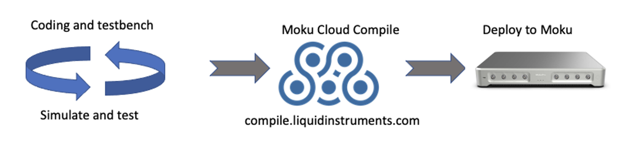
Figure 1: Moku Cloud Compile deployment process
Multi-Instrument Mode and Moku Compile
Multi-Instrument Mode allows multiple instruments to be deployed and operate simultaneously. Multi-Instrument Mode presents multiple slots representing partitions of the FPGA on Moku. You can deploy a flexible arrangement of instruments into these slots. Figure 2 shows the Multi-Instrument Mode interface with an Oscilloscope deployed in Slot 1 and a Spectrum Analyzer deployed in Slot 2, while Slots 3 and 4 remain to be filled. Any of the Moku platform’s ever-expanding list of instruments can fill the remaining slots, including custom designed bitstreams using Custom Instrument. A complete list of instruments is available here.
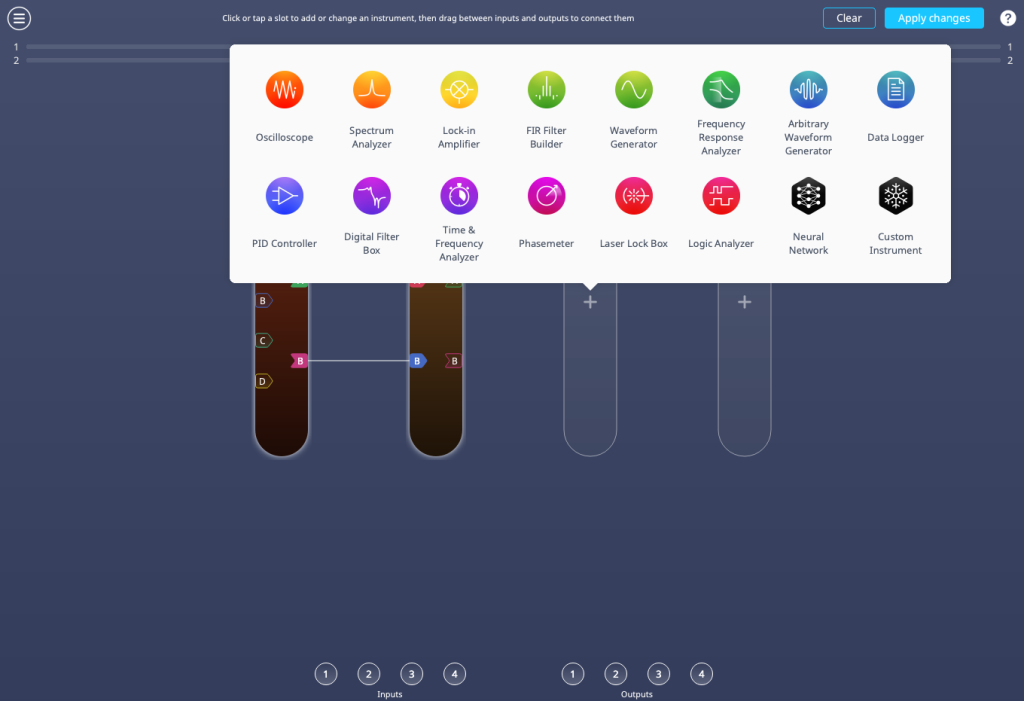
Figure 2: Building a test system with Multi-Instrument Mode.
It is Moku Custom Instrument which occupies Slot 4 in Figure 3, where you can deploy your compiled designs. Custom Instrument can occupy any available slot in Multi-Instrument Mode and enables your designs to interact with other Moku instruments in addition to the ADC and DAC inputs and outputs.
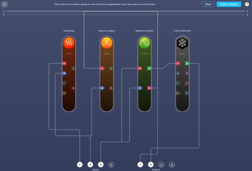
Figure 3: A Multi-Instrument Mode setup built with Moku Custom Instrument in Slot 4.
Setting up a Moku Cloud Compile account
Before you can compile or deploy code to a Moku device, you must first create an online account. This is a simple process:
- Set up a Moku Cloud Compile user account at compile.liquidinstruments.com. If you are using an older version of MokuOS (before v4.0), please use the legacy compiler site instead: compile-legacy.liquidinstruments.com.
- If you’re a first-time user, you will need to select “Sign up.”
- The sign-up page requires only a user-selected username, valid email address, and user-defined password.
- Once signed up and logged in, you will see the projects page, which initially will be empty, as shown in Figure 4.
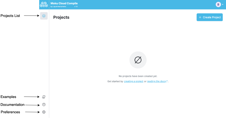
Figure 4: The Moku Cloud Compile project creation screen.
Creating your first project
Once you have an account and log in to Moku Cloud Compile, all your previous work and designs will be available. Additionally, you can create new projects, or rebuild previous designs to account for future enhancements to the Moku platform. The projects page can be seen in Figure 5. You can import existing code from the Github repository by clicking on Import Example. For now, start a new project by clicking on the Create Project button.
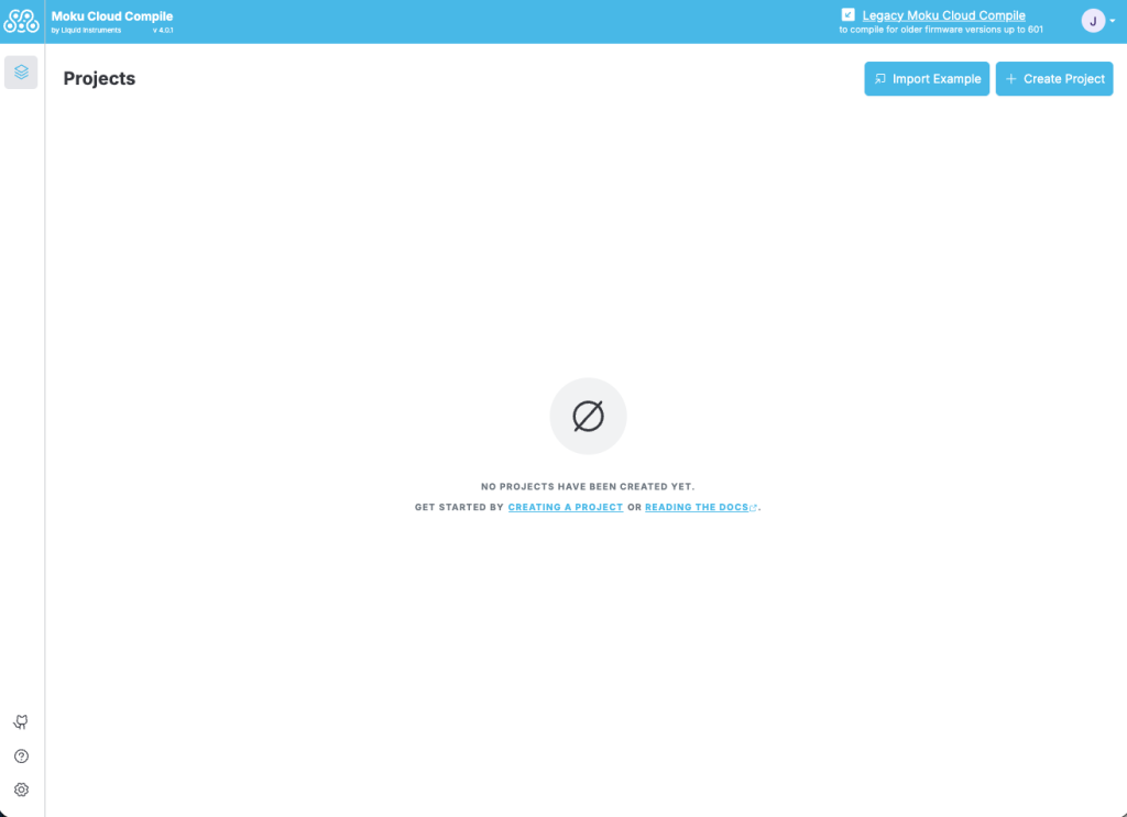
Figure 5: The Moku Cloud Compile project screen.
Next, using the pop-up dialogue box shown in Figure 6, you can provide a name to your project and start coding your design.
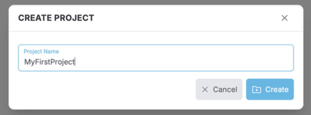
Figure 6: New project dialogue box.
You will then arrive at the project configuration screen, shown in Figure 7. Notice the drop-down menu for build configuration toward the bottom left of the screen.
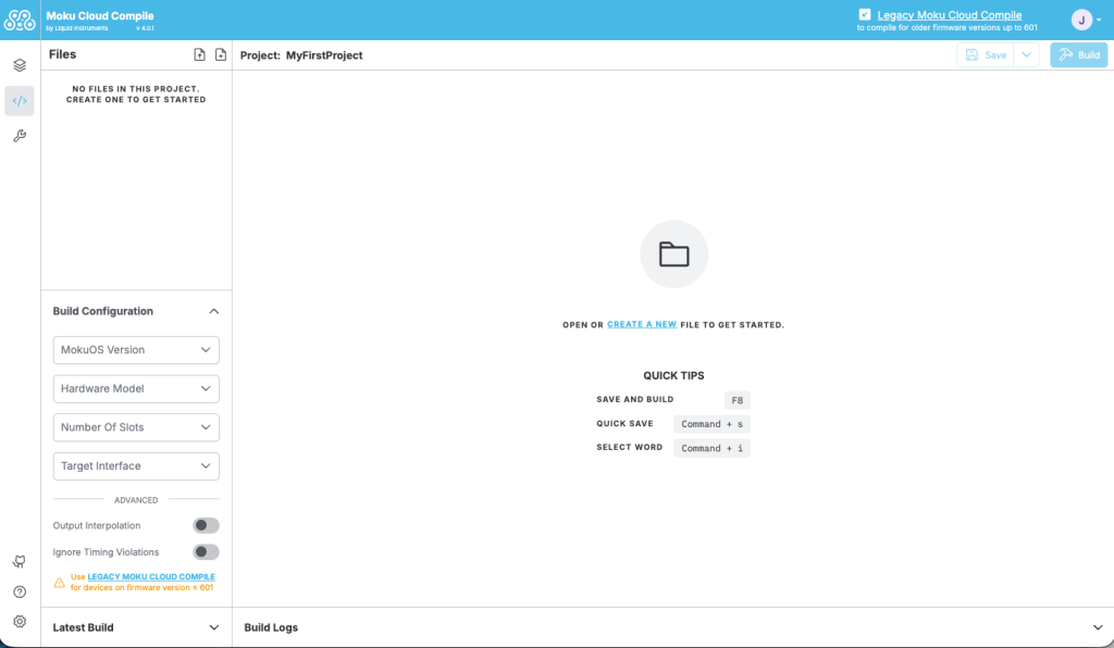
Figure 7: Project configuration screen.
Before building a design, you must first specify the hardware and MokuOS version that you are using. Once you open the build configuration dropdown, the Hardware Model drop-down will allow you to specify any of the current Moku devices. Once you select the appropriate device, the drop-down for Number of slots will populate as appropriate. Moku:Go and Moku:Lab have options for two or three slots. Finally, you must specify the current MokuOS version that you are running on your Moku device. If you are unsure which MokuOS Version you are using, you can find this information in the bottom right of the Moku app, seen in Figure 8. Finally, select CustomInstrument under the Target Interface if this is your first Cloud Compile project (the CustomWrapper entity is available to ensure compatibility with older projects).
Note: You will need to rebuild your design each time you update MokuOS on your device or if you want to deploy your code to different Moku hardware. This is easily accomplished by opening the project, changing the hardware and MokuOS selections, selecting build, and downloading the new resulting bitstream.
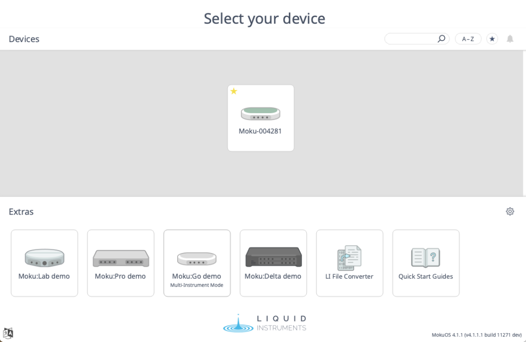
Figure 8: Device selection screen, showing MokuOS version number in the bottom right corner.
Building your design
The entity CustomInstrument is your way to interface your HDL code with the Moku hardware. The entity defines the interface and variables that custom designs need to implement. When you create a new file on Moku Cloud Compile, the code will begin with this entity already defined; there is no need to make any changes. Note that old code or examples may use the entity CustomWrapper. This is similar in function and designed for compatibility for older code versions, all new designs should use CustomInstrument.
While Moku Cloud Compile designs can be deployed as standalone instruments via Multi-Instrument Mode, most designs will yield their true benefit when deployed in conjunction with other Moku instruments.
Your first project
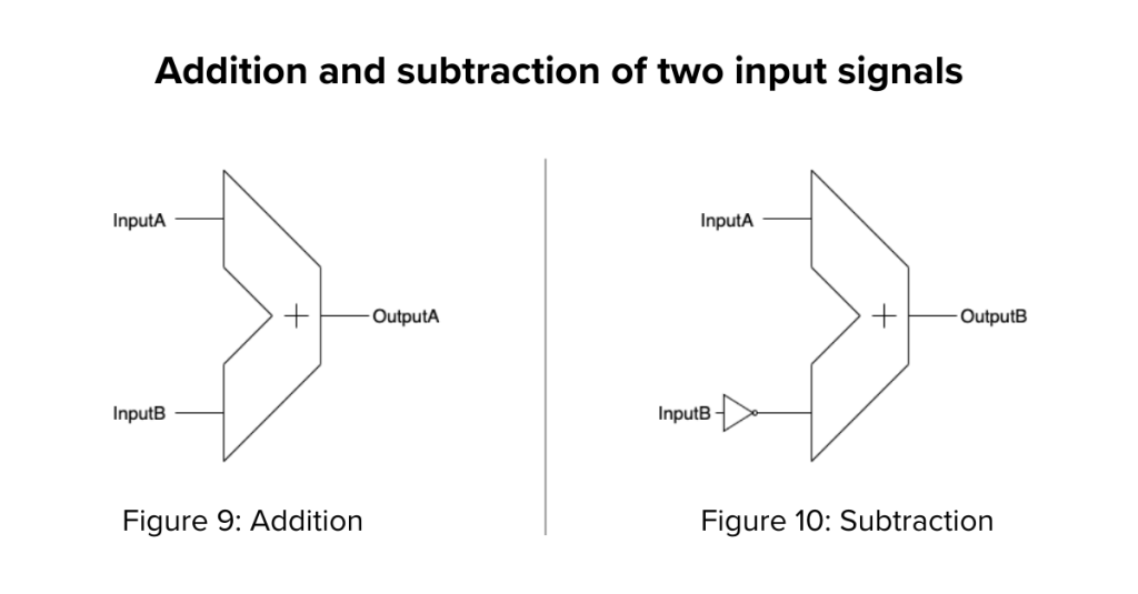
In this first project, we will design a custom instrument that will take two inputs mapped via Multi-Instrument Mode into InputA and InputB and perform basic combinatorial arithmetic. The addition of these two inputs (InputA + InputB) will be output on OutputA, as shown in Figure 9. The subtraction of the two inputs will be output on OutputB, as shown in Figure 10.
Entering VHDL code
We will program this example using VHDL, although Verilog could be used as well. There are two methods for inserting HDL code into your project. First, you can enter the code within the Moku Cloud Compile interface by clicking on the button highlighted in Figure 11. You must first create a file to store this code. In this case, we will create a single file called Adder.vhd.
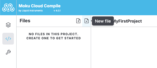
Figure 11: Create a VHDL file within the project.
This is the file where we will enter the code for our VHDL design. Once the file is created, you will see a blank template available for customization as shown in Figure 12.
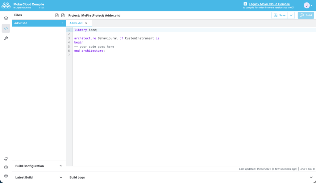
Figure 12: Entering code into the file template.
For this first project, you can copy and paste the complete code directly into your Adder.vhd file, and save when complete. For purposes of this simple example, you can overwrite all current code in the Adder.vhd file and include the code below.
library ieee;
architecture Behavioural of CustomInstrument is
begin
OutputA <= InputA + InputB;
OutputB <= InputA – InputB;
end architecture;
Uploading VHDL code
The Moku Cloud Compile user interface also allows you to directly upload .vhd or .v files that you have already created. This feature is particularly useful if you have a complex project with many files, or if you like to work with a specific text editor. Figure 13 shows the button to press in order to upload your own VHDL code from a file already created.
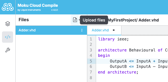
Figure 13: Uploading VHDL code within the Moku Cloud Compile interface.
Generating a bitstream from VHDL code
To build your VHDL design, you simply need to save all individual VHDL files in the Moku Cloud. Make sure that your build configuration is correct, and then select Build in the upper right hand side of the project window. Building your project will run through the process shown in Figure 14. Any errors in the build process will be highlighted, with a description of the issue in the Build Logs
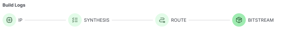
Figure 14: Phases of the Moku Cloud Compile build process.
Once the code compilation is complete, the “IP,” “Synthesis,” “Route,” and “Bitstream” icons should all be green. It is likely you will see many compiler or synthesizer warnings, which appear as yellow text in the build log. These can mostly be disregarded for our purpose. However, any errors would need attention as they will halt the build process.
Saving the bitstream for future use
You can save this bitstream to your computer for future use and deployment in a variety of Multi-Instrument Mode configurations without rebuilding the design. You will first need to expand the dropdown for Latest Build in the bottom left of the screen below the Build Configuration. Then, as shown in Figure 15, you simply need to download the bitstream.tar file and save it to a known location for import into the Moku app. Do not unzip or untar this file, although it can be renamed to describe its functionality.
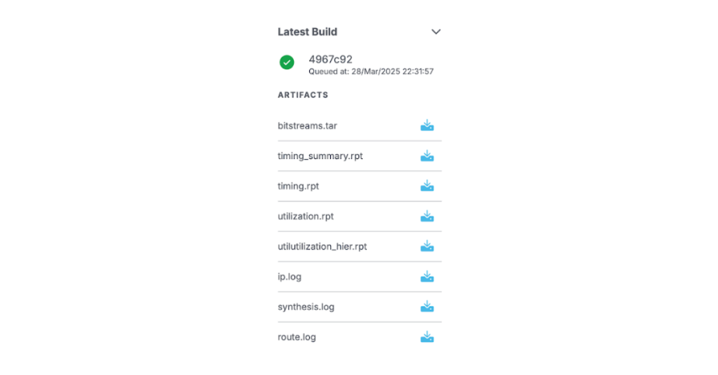
Figure 15: Downloading the bitstream.
Deploying your design
Compiled bitstreams are deployed using Custom Instrument and are typically used in conjunction with the other instruments available on the Moku via Multi-Instrument Mode. Even in cases where the bitstream is designed to stand alone, you must access the design’s functionality through Multi-Instrument Mode on your Moku device.
Multi-Instrument Mode configuration
Moku Custom Instrument can reside in any available slot on the Moku. Slot choice will be driven by the larger chain of instruments and functionality you wish to design within Moku. For the purposes of this first example, we can use the Multi-Instrument Mode configuration on Moku:Go shown in Figure 16.
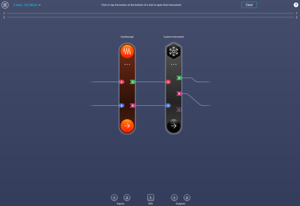
Figure 16: Multi-Instrument Mode configuration.
In Slot 1, we have the Moku Oscilloscope that has Output A and Output B routed to Input A and Input B of Slot 2, containing Custom Instrument. Output A and Output B of Custom Instrument are routed back to Input A and Input B of Slot 1 by default. This setup will allow us to validate the performance of the design with a single Moku:Go device.
Deploying the bitstream
Once you have configured Multi-Instrument Mode, and built and downloaded your Moku Compile bitstream, you are ready to deploy your bitstream. To do so, click on the three dots below the Moku Custom Instrument icon. Click “Browse bitstreams” to open the Moku Compile Bitstream Browser, as seen in Fig 17. This feature can link to your Moku Cloud Compile account to directly download bitstreams to your device. This procedure is explained below. For now, click Local bitstream… and navigate to the file you downloaded earlier. Once loaded, click Apply changes in the top right of Multi-Instrument Mode and your custom instrument will run.
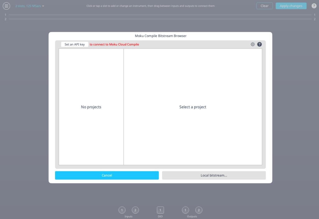
Figure 17: The Moku Compile Bitstream Browser.
Linking your Cloud Compile account
If you wish to use Bitstream Browser to download your bitstreams directly to your device, you first need an API key from the Moku Cloud Compile website. After logging in, click the letter in the top right corner (your initial), then Preferences from the dropdown menu, as seen in Fig 18.
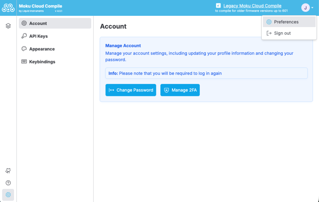
Figure 18. Moku Cloud Compile preferences menu.
On the left-hand side menu, click API Keys. This allows you to see all of the keys you’ve created. Click Create API Key, then enter a name. Enable all the boxes with Select all. When you are ready, click Create, as seen in Fig 19.
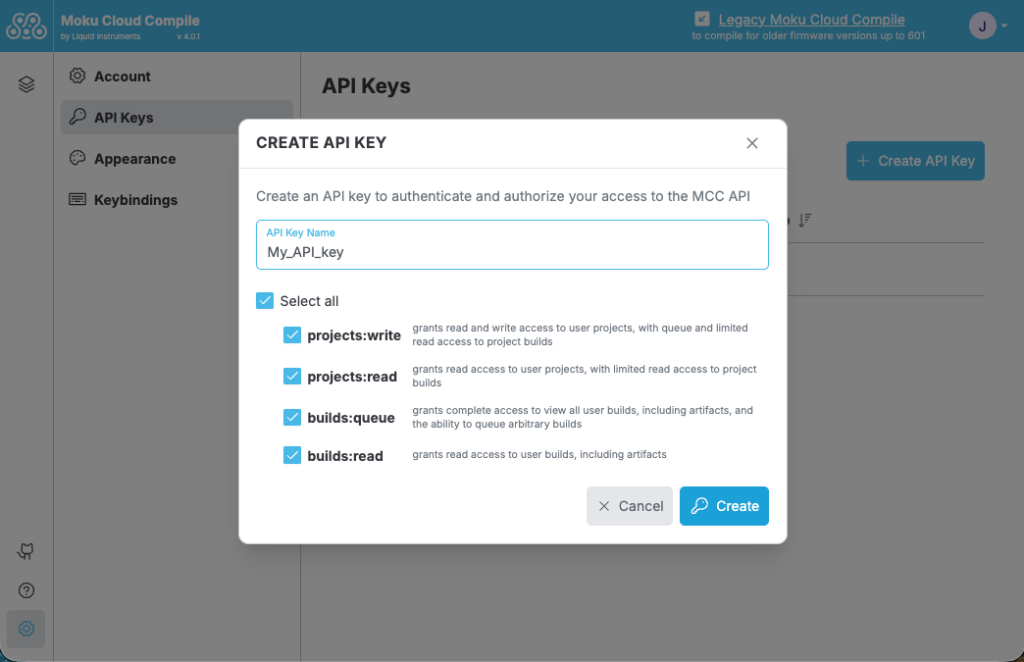
Figure 19. API key creation menu.
You will then be shown a pop-up with your API key. Click Copy and paste this key somewhere, as you will not be able to view it again. Once copied, close the menu to return to the API Keys menu, where you will see the name of your new key listed.
Return to the Multi-Instrument Mode screen on your Moku device, and set the configuration as per Fig 16 in the previous section. Select Browse bitstreams, and then click Set an API key as seen in Fig 20. Copy and paste the key you obtained, then click Accept.
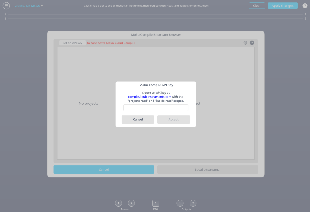
Figure 20. API key information in the bitstream browser.
After doing this, you’ll see your existing projects begin to populate on the left-hand side, displaying the latest build information. View “MyFirstProject,” which should have been compiled recently, as seen in Fig 21. Click Use bitstream to load it onto your Moku. After uploading, you should return to the Multi-Instrument mode configuration screen. Click Apply changes to configure your Moku before continuing to the next section.
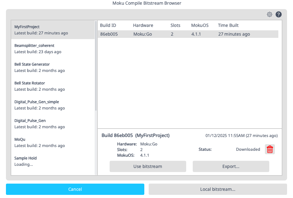
Figure 21: Selecting a bitstream with the bitstream browser.
Results
We will use the signal generator functionality within the Moku Oscilloscope to demonstrate the Moku Cloud Compile adder functionality. To verify the Moku Cloud Compile design functions as expected, place a simple 2 VDC signal on both output channels. Input A on the Oscilloscope should read the addition of the two signals with a steady 4 V signal. Input B of the Oscilloscope should read the difference of the two signals with a steady 0 V signal as shown in Figure 22.
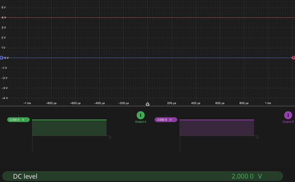
Figure 22: Sample DC results for adder.
You also can change the signal type to “sine,” and experiment with different effects. Combining two sine waves of different frequencies will generate beat notes, whereas changing the phase of two identical sine waves will result in constructive or destructive interference. You can see an example of this in Figure 23. You can also select the “noise” signal type if you wish to add artificial noise to a generated signal.
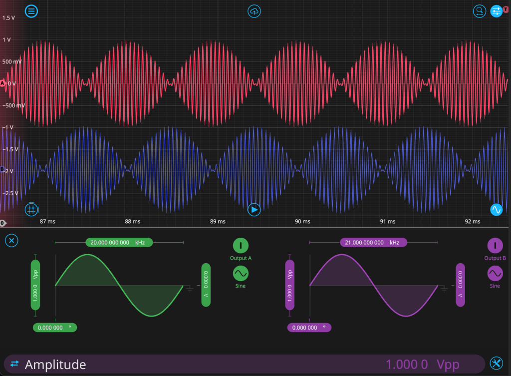
Figure 23: Sample beat note results for adder.
Conclusion
While the example presented here was very simple, this application note is intended to help you quickly get started with Moku Cloud Compile and leverage the true flexibility of the reconfigurable Moku platform.