


The Moku:Pro Laser Lock Box integrates multiple crucial electronic components of the Pound-Drever-Hall laser locking technique into one instrument, making the laser locking process easier than ever without compromising performance. This app note will cover the principles of PDH locking, outline the procedure for locking a laser to a high-finesse cavity using the Moku:Pro Laser Lock Box, and present results showing the dramatic improvement in laser frequency stability when using this locking technique. To learn more, download the ebook on the ultimate guide to Pound-Drever-Hall (PDH) laser locking.
Pound-Drever-Hall laser locking technique
In a standard lab environment, a laser’s frequency can drift due to a range of factors, such as ambient temperature, injected current, and quantum fluctuations. Laser frequency stabilization is therefore a necessary process in applications that utilize lasers to conduct precise measurements, such as gravitational wave detection, atomic physics, and molecular trace gas detection. There are multiple methods available to perform laser frequency stabilization — one of the most common methods is to lock the laser frequency to an optical reference cavity with a stable mechanical setup. The Pound-Drever-Hall (PDH) method is one of these methods. It uses the derivative of the reflected laser intensity as an error signal to lock the laser frequency to the cavity resonance and suppress frequency fluctuations [1].
When locking a laser to a cavity, the light from the laser can only pass through the cavity when an integer number of its wavelength matches the round-trip length of the cavity. This is also the point when the reflected light from the cavity is at a minimum. Figure 1 shows the correlation between the reflected intensity and the frequency of the laser relative to the cavity resonance. However, it can be hard to use this signal as an error signal in a feedback system since the reflected light intensity is symmetric around the resonance, and it is positive both above and below the cavity resonance. If the laser frequency drifts away from the cavity resonance, it is impossible to know if the laser frequency needs to be increased or decreased. However, due to the minimum of the reflected signal intensity, the derivative of the reflected light will have a zero crossing with different polarity on either side of the resonance. It is negative when the frequency is below the resonance and positive when the laser frequency is above the resonance. The derivative of the reflected intensity can be measured by introducing small modulations to the laser frequency, also known as dithering. The PDH technique utilizes this derivative of the reflected intensity with respect to laser frequency as the error signal to dynamically adjust the frequency of the laser to match the resonance of the cavity.
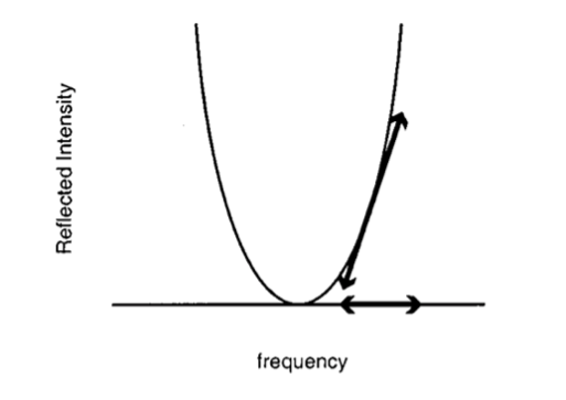
Figure 1: The reflected light intensity from an optical cavity as a function of laser frequency [2]
Figure 2 illustrates the components and layout of a PDH laser locking system. Here, the frequency is modulated with an electro-optical modulator (EOM) driven by the local oscillator. A photodetector captures the reflected light, and its output is demodulated with the local oscillator via a mixer. The mixed signal is then passed through a low-pass filter to separate out the DC, or very low frequency, component from the second harmonic of the modulation frequency. This DC component is used as the error signal, which provides an unambiguous indication of not only how far the system is from resonance but in which direction adjustments must be made to restore resonance. The error signal is then sent into a servo amplifier or proportional-integral-derivative (PID) controllers and into the tuning port on the laser, locking the laser to the cavity.
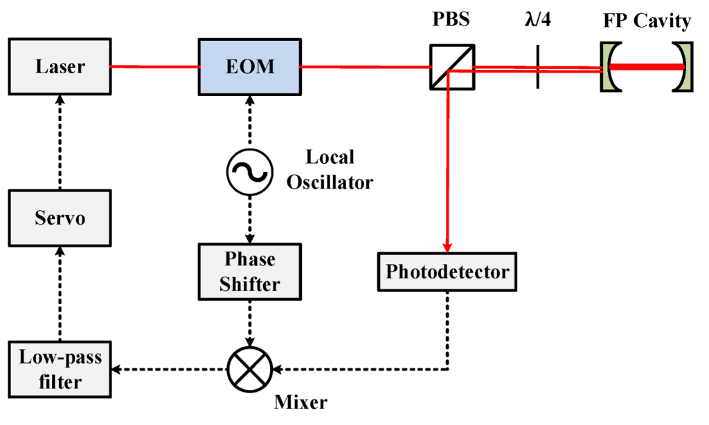
Figure 2: A block diagram of the PDH laser locking technique [3]
Moku:Pro Laser Lock Box
The traditional PDH laser locking process requires several dedicated, custom-made electronic instruments including signal generators, mixers, low-pass filters, servo systems, and oscilloscopes. The Moku:Pro Laser Lock Box integrates most of the PDH electronics into one compact, easy-to-use instrument that provides high-precision laser frequency locking. It includes a Waveform Generator for scanning and modulating the laser frequency, a mixer and low-pass filter for demodulating the error signal, and two cascaded PID Controllers to provide the fast and slow control signals back to the laser’s actuators, such as piezo or temperature controllers. Using the built-in Oscilloscope, users can also monitor the scanning response of the reflected light and display the PDH signals in real time (Figure 3).
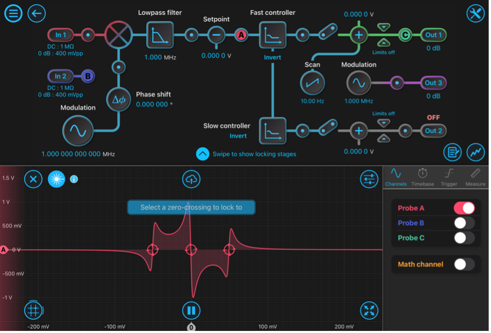
Figure 3: Main user interface of the Moku:Pro Laser Lock Box
Experimental setup for PDH laser locking
In this experiment, we used the Moku:Pro Laser Lock Box for locking a laser to a high-finesse cavity. Figure 4 illustrates the PDH laser stabilizing system with Moku:Pro.
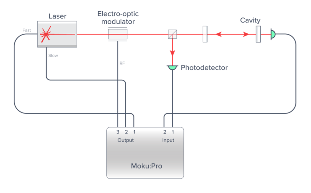
Figure 4: Experimental setup illustration of PDH technique with the Moku:Pro Laser Lock Box
A Coherent Mephisto S fiber laser (1064 nm) was modulated by an electro-optical modulator (EOM) and redirected into a 10 cm linear plano-concave cavity (finesse 100,000). Two photodetectors (PDs) were placed to detect the transmitted and reflected light from the cavity. The signals detected on the PDs were fed into Moku:Pro Input 1 for the reflected signal (mixer input) and Input 2 for the transmitted signal (monitor). Output 1 of the fast PID was then connected directly to the laser’s piezo to actuate laser frequency, and Output 2 of the slow PID was connected to the temperature control of the laser.
Figure 5 depicts the configuration and settings of the Laser Lock Box. A local oscillator (LO) with an amplitude of 500 mVpp at approximately 2.885 MHz was generated with the Moku:Pro Laser Lock Box Waveform Generator. The LO signal was then sent from Moku Output 3 to drive the EOM. The same LO signal was also used to demodulate the cavity reflection using a digitally-implemented mixer followed by a digital 4th-order Butterworth low-pass filter with a corner frequency of 300.0 kHz. Using the integrated scanning feature of the Moku:Pro Laser Lock Box, we set the scan generator to output a signal to the PZT actuator (Output 1) at a frequency of 10 Hz. With the scanning signal enabled, we could view the PDH error signal using the built-in Oscilloscope probe point at the output of the filter. Then, we adjusted the offsets applied to the temperature controller and centered the resonance in the middle of the scan. To further optimize the error signal, we also adjusted the phase of the local oscillator until the error signal was symmetric and with a maximized linear range around the resonance for locking. In this example, a phase shift of approximately 113.6 degrees gave us the best error signal. We configured the fast PID Controller with a proportional gain of -27 dB, integrator crossover frequency of 7.5 kHz, and a double integrator crossover frequency of 70.60 Hz. We configured the slow PID Controller to have an integrator crossover frequency of 4.883 mHz.
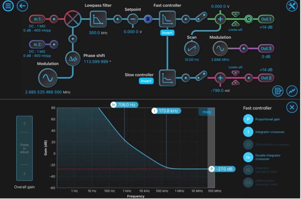
Figure 5: Fast PID Controller configuration
To engage the PDH lock, we gradually reduced the scanning amplitude, then enabled the fast and slow PID Controllers in sequence. As an advanced feature, users can also engage the lock by configuring locking stages or by using the Lock Assist feature. This feature allows user to select a zero-crossing of the demodulated error signal as the locking point, which will automatically engage the fast PID Controller and lock the laser frequency to the cavity resonance. We then disabled the integrator saturation to align the laser frequency to the DC frequency of the cavity.
Results and discussion
Using the built-in Oscilloscope probe points, we could measure the error signal RMS and optimize the overall loop gain, as shown in Figure 6. Increasing gain would potentially minimize the RMS of the error signal, but too much gain can cause oscillations, while too little gain meant that laser frequency perturbations remained insufficiently suppressed.
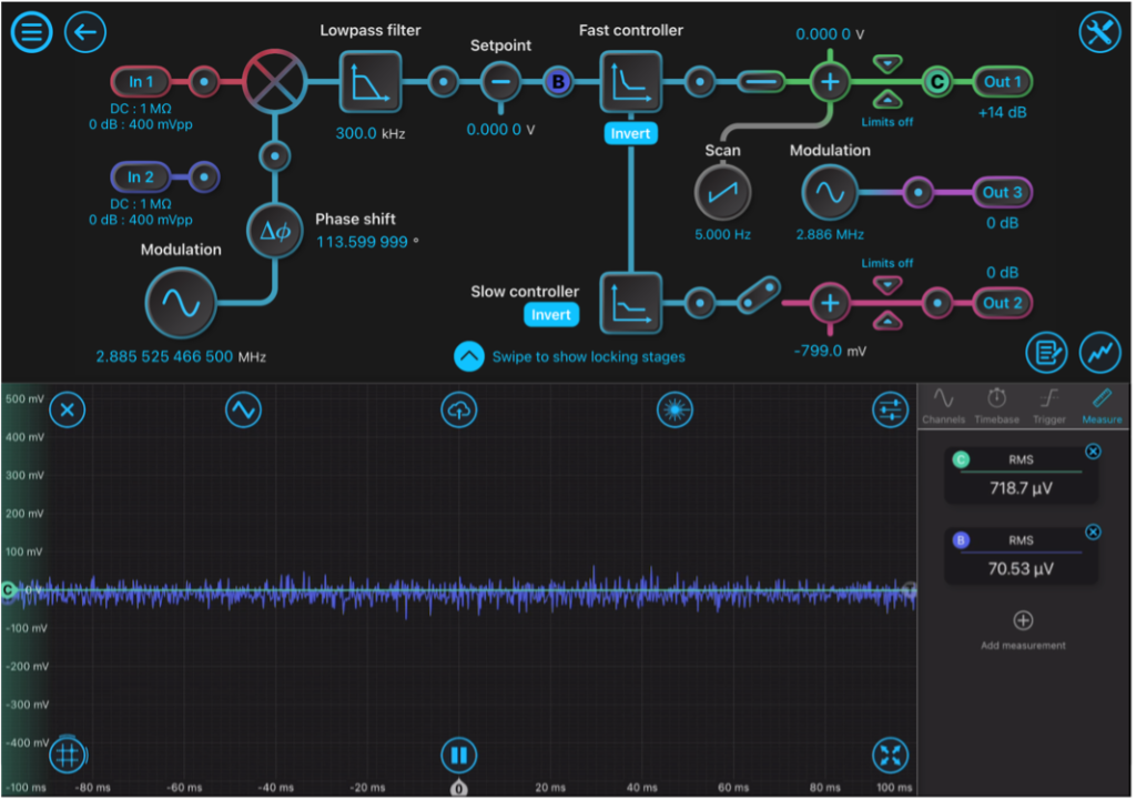
Figure 6: Measured RMS of the error signal
Users can further optimize loop performance by verifying the closed-loop response using the Multi-Instrument Mode feature for Moku:Pro. Moku:Pro can inject a swept sine disturbance with the Frequency Response Analyzer between Moku:Pro Output 1 and the laser piezo using a summing pre-amplifier and measure the suppression of this injected perturbation within the loop. Find further details on frequency-domain optimization in this app note.
We verified the optimized control loop performance using a one-cavity-two-lasers test. A second laser was locked to the cavity one Free Spectral Range (FSR) above the first laser’s lock with a second identical Moku:Pro Laser Lock Box setup. With a lock at two independent frequencies, the two lasers were compared with identical common cavity noise but independent electronic noise and uncorrelated laser frequency noise. The residual frequency variation between these two locked lasers was independent of cavity spacer noise, thermal noise of the cavity coatings, and common vibrations from the laboratory environment. This noise, due only to the control loop and sensors, was measured by combining light from both laser paths into a high-speed photodetector, mixing down with a stable GHz function generator and using a Moku:Lab running the Phasemeter instrument to track the frequency deviations. Figure 7 compares the frequency noise before and after the laser was locked to the cavity with Moku:Pro. The system stability improved by approximately six orders of magnitude at 0.001 Hz. The frequency noise also reduced to 10-2Hz/√Hz.
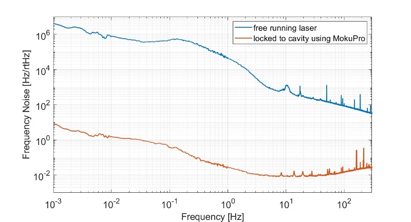
Figure 7: Frequency noise of the beat note before (blue) and after (orange) the lock was engaged
Acknowledgements
We would like to thank Andrew Wade, Kirk McKenzie, Emily Rees, Namisha Chabbra, Jue Zhang, and The Australian National University for providing us with details about their experiment, an explanation of how they used Moku:Pro, and feedback on this app note.
References
[1] P. Drever et al., Laser Phase and Frequency Stabilization Using an Optical Resonator, vol. 31, Appl. Phys.B., I983, pp. 97-105.
[2] E. D. Black, An introduction to Pound–Drever–Hall laser frequency stabilization, vol. 69, American Association of Physics Teachers., 2000, pp. 79-87.
[3] Z. Chang Liu et al., Far Off-Resonance Laser Frequency Stabilization Technology, Appl. Sci., 2020.

Questions or comments?
Contact us at support@liquidinstruments.com.