


The Moku:Go Logic Analyzer incorporates its own Protocol Analyzer, which contains six protocols: SPI, I2C, I2S, Parallel bus, UART and CAN. Along with a high sampling rate and advanced trigger options, the digital input/output (DIO) pins of Moku:Go run alongside other instruments in Multi-Instrument Mode for even more flexibility. The Logic Analyzer instrument is also available on Moku:Lab and Moku:Pro.
Moku:Go
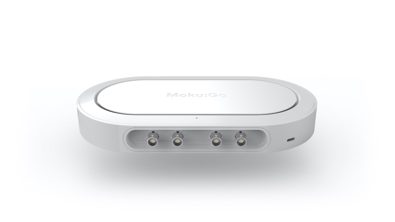
Moku:Go combines 15+ lab instruments in one high-performance device, with two analog inputs, two analog outputs, 16 digital I/O pins, and optional integrated power supplies.
Updates to the Moku:Go Logic Analyzer
The Protocol Analyzer is available through the Logic Analyzer instrument in the Windows and macOS desktop apps. The Logic Analyzer also features several other functions such as:
- Protocols: UART, SPI, I2C, I2S, CAN, Parallel bus
- Sampling rate at 125 MSa/s for all 16 digital input/output (DIO)
- Time cursors
- Advanced triggering options
- Trigger on multiple pins using AND, OR, XOR, NAND, NOR, XNOR logic
- Trigger if the signal is high, low, or on rising/falling edges
Let’s look at some of these features in action and see how you can use them in your next digital logic project.
Decoding UART from an Arduino
Universal Asynchronous Receiver/Transmitter (UART) is a common protocol to transmit and receive serial data. For example, UARTs are frequently used in Arduino projects to control various peripherals, such as a parallel-based LCD with serial I/O. Here, we use the Logic Analyzer with an Arduino development board and a simple LCD to display text. First, we must verify the UART bus before connecting it to an LCD to make sure the Arduino code is working properly.
Setting up the protocol analyzer is straightforward: first, add a new protocol decoder (up to two); then, select which pin to route the data to. Figure 1 shows how to add a protocol decoder channel in the Moku:Go desktop app.
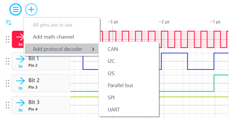
Figure 1: Setting up the protocol decoder
After adding a protocol decoder, configure the protocol-specific settings that fit the data transmitter and receiver specifications. In Figure 2, there are options for configuring the UART protocol including data width, parity, baud rate, and more.

Figure 2: UART decoder settings
For this project, the UART protocol decoder is using the same settings from Figure 2, such as a baud rate of 9,600 bps, which is common for a 5 V Transistor-to-Transistor Logic (TTL) serial interface. Let’s make sure the “Hello” text on the LCD screen is also shown here in the Protocol Analyzer. The last step is to connect the Arduino’s transmitter pin to the Moku:Go receiver pin (Pin 1). Figure 3 displays the pinout diagram of the Moku:Go DIO header that corresponds with the DIO cable included with Moku:Go. The Protocol Analyzer reports values in hexadecimal, so converting the 5 data packets in Figure 4 using ASCII characters confirms that the LCD screen will display “Hello” once connected.
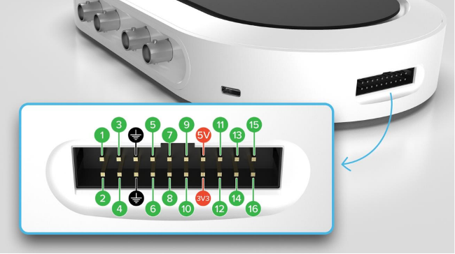
Figure 3: Moku:Go DIO header pinout

Figure 4: Protocol Analyzer example
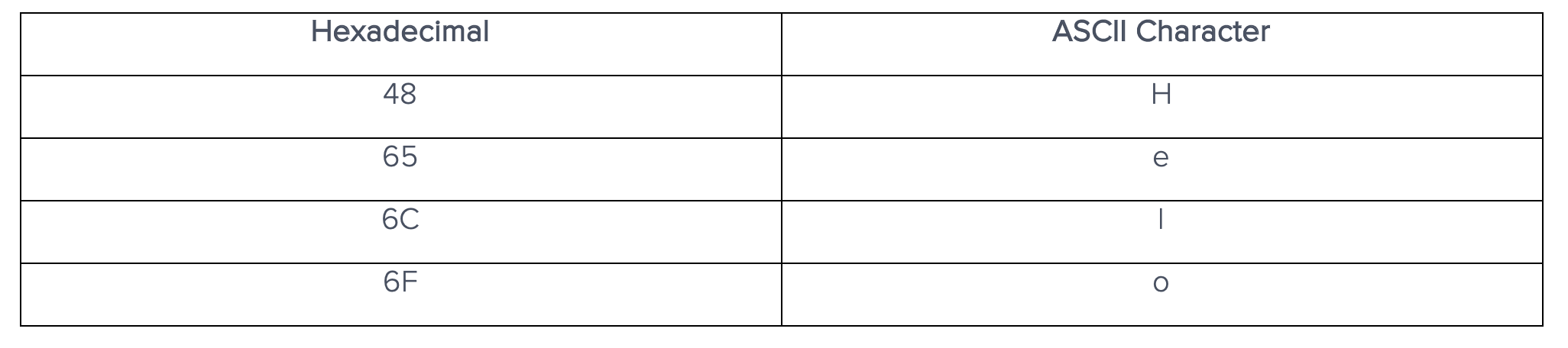
Converting hexadecimal to ASCII characters is straightforward and is done using a table or any number of online conversion tools. A truncated hexadecimal to ASCII characters table for this project looks like Table 1.
Table 1: Hexadecimal to ASCII character conversion
When using the Moku:Go Protocol Analyzer, you can trigger the input pins and display the values on-screen next to the protocol decoder pin. This allows for quick debugging, revealing timing errors like mismatched baud rates or incorrect parity bits.
Adding DIO lines to Multi-Instrument Mode
The Multi-Instrument Mode (MiM) feature of Moku:Go also enables the DIO pins as inputs and outputs for other instruments. While using the digital inputs for triggering, you free up both BNC-type analog I/O channels for data capture. Figure 5 illustrates using a DIO pin to trigger a Waveform Generator, while both analog inputs are simultaneously connected to a Data Logger.
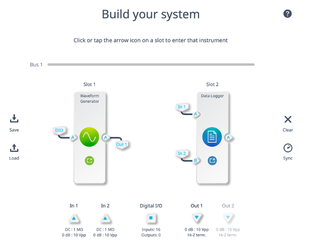
Figure 5: Waveform Generator using DIO inputs
Clicking on the DIO square allows you to further configure each pin and shows a pin map of all active pins similar to Figure 6.
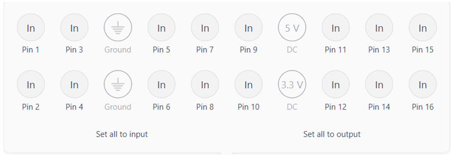
Figure 6: MiM DIO settings
Summary
The Moku Protocol Analyzer, along with high sampling rates and MiM integration, provides a flexible tool for your next digital logic project. The available protocols are UART, I2C, I2S, CAN, Parallel bus, and SPI with more coming in future updates. For more practice using the Moku:Go Logic Analyzer, explore the 4-bit Adder project. If you have suggestions for what protocols you would like to see next, let us know on our forum.
Moku:Go demo mode
You can download the Moku app for macOS and Windows here. Demo mode operates without any hardware and provides an introduction to using Moku:Go.
Questions or comments?
Contact us at support@liquidinstruments.com.