


With Moku Cloud Compile, it’s easy to deploy your own custom digital signal processing (DSP) on a Moku FPGA. FPGA programming is typically done with hardware description language (HDL). The learning curve for HDL coding can be steep compared to software programming languages, therefore in this tutorial, we will cover how to program and build a DSP behavior/algorithm using MATLAB and Simulink to auto-generate VHDL code for implementation on the Moku platform. In Part 1 of this tutorial, we will demonstrate how to convert a MATLAB script into VHDL code, and Part 2 of the tutorial will demonstrate how to convert a Simulink model into VHDL code.
Overview
Moku Cloud Compile
Liquid Instruments’ Moku Cloud Compile (MCC) tool enables users to design custom instruments for implementation on Moku platforms. Compared to CPU and application-specific integrated circuit (ASIC) based DSP approaches, FPGAs provide ASIC-level input-to-output latency while being software-defined and reprogrammable like a CPU. FPGA programming is typically done with hardware description language (HDL). The learning curve for HDL coding can be steep compared to software programming languages, but there are a few tools available to convert scripts in other programming languages to HDL. In this tutorial we will demonstrate how to use MathWorks HDL Coder to convert your MATLAB code into HDL code for implementation on a Moku:Pro.
In Part I of this tutorial, we will only focus on VHDL code generation with MATLAB HDL Coder. This method is recommended for users that are already familiar with programming in MATLAB. Part 2 of this tutorial will cover VHDL code generation from Simulink models. The block-diagram format of Simulink models can make it easier to visualize the system and data flow and users can also add MATLAB function blocks into their design. For more complex systems, utilizing both tools may significantly streamline the design process.
The design process of the MATLAB HDL Coder method can be broken down into 4 top-level stages in Figure 1: DSP design, floating point simulation, HDL generation, and DSP deployment and verification. We will follow these steps to build a digital Schmitt trigger using MATLAB HDL Coder for implementation on Moku:Pro.
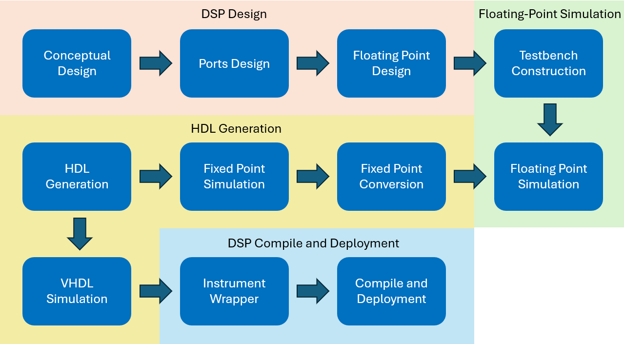
Figure 1: Recommended workflow for Cloud Compile + HDL Coder DSP Design.
Schmitt Trigger
Schmitt trigger is a variation of a comparator circuit. It provides a 1-bit digital output based on whether the input is above or below certain voltage thresholds. A standard op-amp-based comparator has a single threshold. For a noisy input signal, it may jump around at the threshold voltage and create an unstable output when the input is near or crossing the threshold. A Schmitt trigger has two thresholds, a higher threshold for switching on and a lower threshold for switching off. In this case, even if the noisy input surpasses the switch-on threshold and jumps back, the gap between the higher and lower threshold creates a “protected area,” keeping the digital output unchanged. This device is commonly used as a device trigger or a sine-to-square wave convertor.
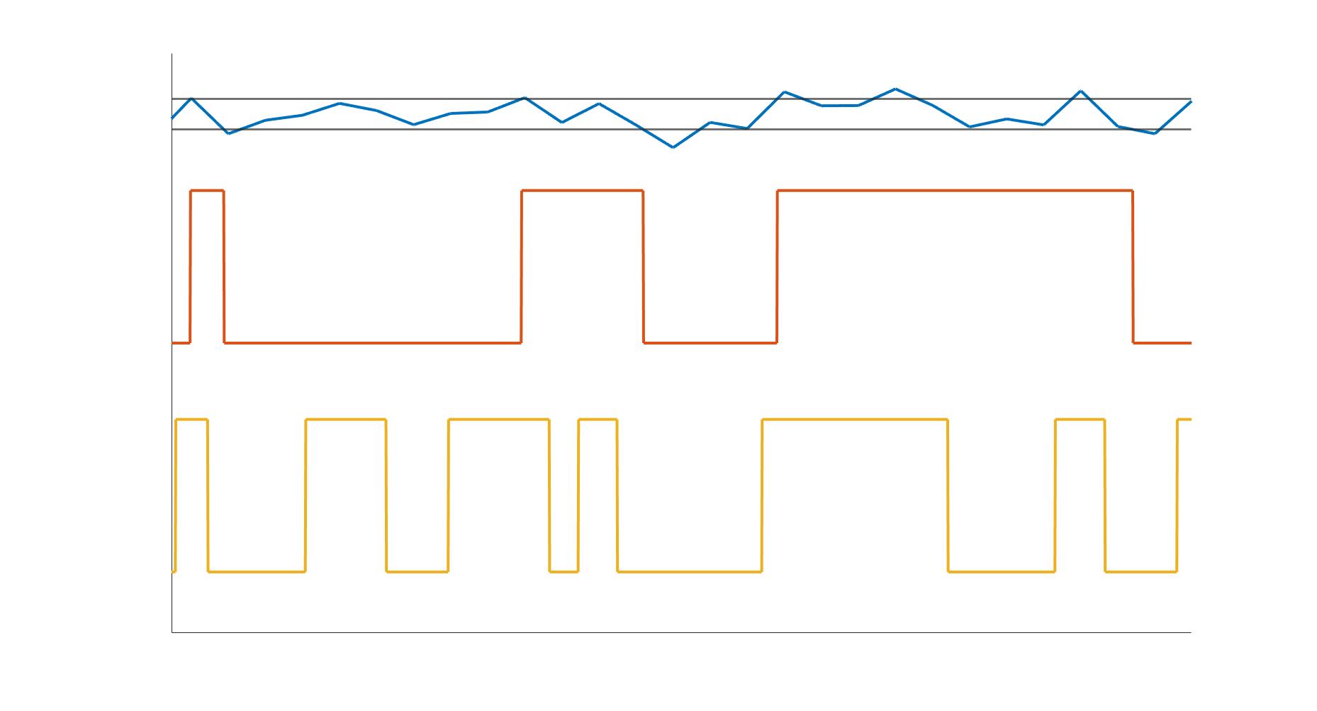
Figure 2: A comparison between a comparator and a Schmitt trigger.
Requirements
Before we get started with building and implementing the Schmitt trigger, please ensure your system satisfies the following requirements. For generating VHDL code from a MATLAB script you will need to have MATLAB with HDL Coder and Fixed-Point Converter. You will also need to have Simulink if you wish to build your system using Simulink in Part 2 of the tutorial. Note: Mac users will also need to have XCode installed for HDL Coder to work. For compiling the VHDL code you will need to have access to Liquid Instruments Cloud Compile. For implementing the compiled instrument bitstream, you will need to have a Moku:Pro running firmware version 601 or above, the Moku: app, and access to Multi-Instrument Mode on your Moku:Pro.
DSP design
Conceptual design
A Schmitt trigger has a single input and output. The analog input signal is compared to the upper and lower thresholds. In this example, the upper threshold is 1/10 of the full positive input range and the lower threshold is 1/10 of the full negative range. If the input signal is higher than the upper threshold, the output is set to 2^15-1 (the largest 16-bit signed integer that the output can generate); if the input signal is lower than the lower threshold, then the output is set to 0; or if none of these conditions are met, it remains in the previous state.
Floating-point DSP design
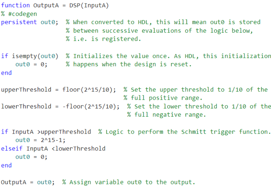
In this section we transform the conceptual design above into a MATLAB function using a persistent variable and an if-elseif statement.
In the Schmitt trigger DSP function, we will only need one input channel (InputA) and one output channel (OutputA). We will create a MATLAB ‘DSP’ with a single input and output. Please note the DSP modules must be designed in a function format.
function OutputA = DSP(InputA)
We can then populate the function with a persistent variable out0, and an if-elseif statement for the logic operation.
Floating-point simulation
Simulation and verification are crucial steps in FPGA design. It is common practice to verify the digital system’s response by constructing a “testbench,” which inputs a simulated signal to observe the system’s response. A testbench is required to convert floating-point designs to fixed-point designs. For a native fixed-point design, the testbench is optional. However, it is highly recommended to always run a testbench simulation for any design.
Testbench construction
In MATLAB, a testbench can be considered as MATLAB script that calls the function (i.e., the DSP function in this tutorial) in a loop with a range of inputs. In this tutorial, we will conduct three rounds of testbench verification: floating-point design, fixed-point design, and HDL design. The first testbench is to verify the floating-point model, the second is to verify the system behavior after fixed-point conversion, and the last is to verify the HDL model through VHDL simulation in an EDA software.
The first two rounds of the testbench are conducted in MATLAB and with a simulated input signal using the same testbench script. The simulated signal should be a close proximation to the real input signal in terms of dynamic range and precision. This will help MATLAB’s Fixed-point Tool to determine the best suited precision for the fixed-point model.
The DSP function testbench works by loading a set of example data as the input signal. This signal is consistent with the Simulink model in Part 2 of the tutorial. The DSP function is then called in a for loop and the output is plotted in Figure 3. The output confirms the DSP function matches the Schmitt trigger that we wanted to design and therefore we can now proceed to generating HDL code using MATLAB HDL Coder.
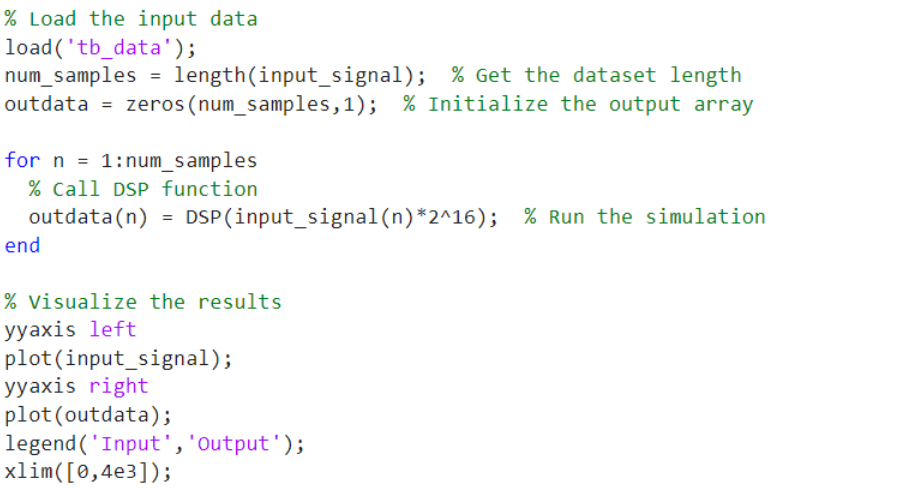
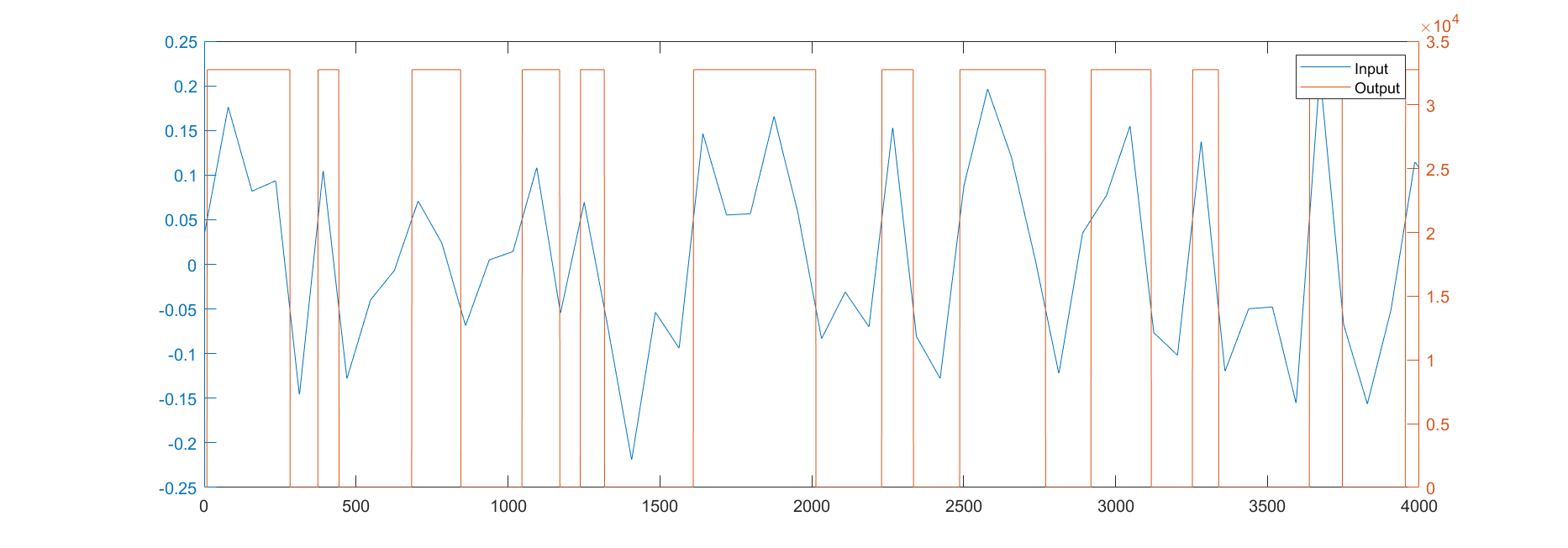
Figure 3: Output from the MATLAB simulation
HDL code generation
MATLAB HDL Coder guides the user through the complete HDL code generation process with a Workflow Advisor, which includes the fixed-point conversion, HDL generation, and HDL testbench generation process. To initiate this process of converting our DSP function into a HDL code, we first start the HDL Coder App in MATLAB and create a new project. Alternatively, you can type in “hdlcoder” in MATLAB’s Command Window.
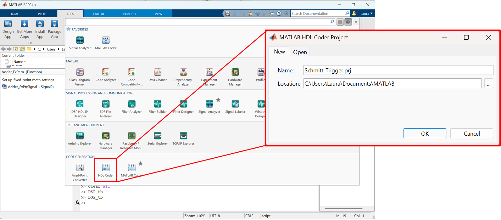
Figure 4: The HDL Coder app can be found in the App tab to create a new HDL Coder project.
Once the HDL Code Generation window pops up, we can add the MATLAB function (DSP) and the corresponding testbench. We can define the function’s input variable type here with “Autodefine types”, or we can complete this in the Workflow Adviser. In most cases, the input variable can be defined as double, as our model is floating point at this point.
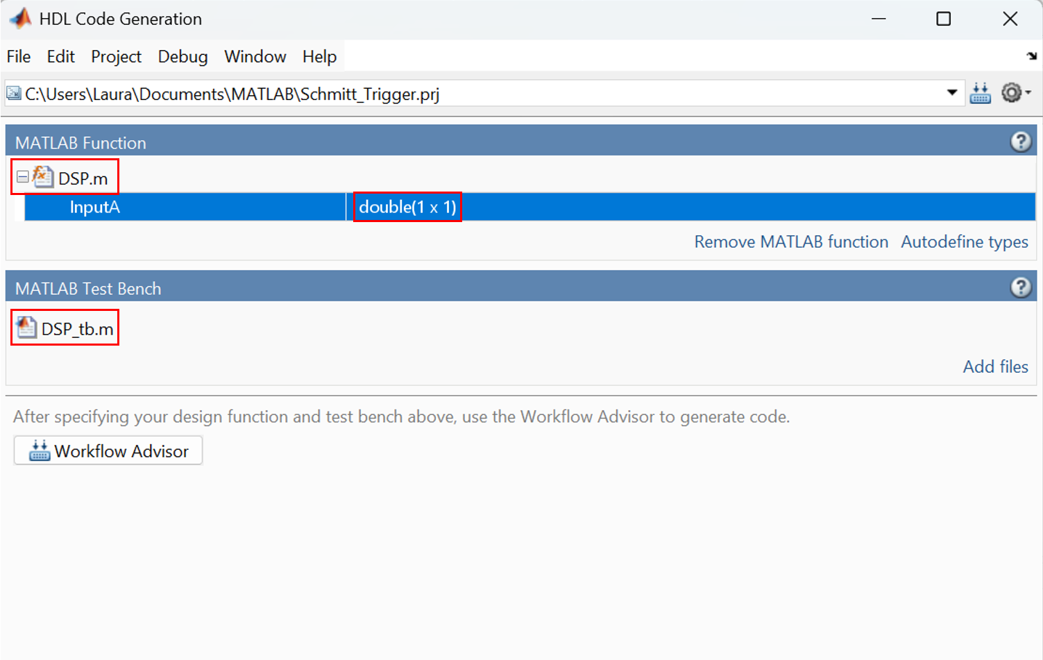
Figure 5: DSP.m and DSP_tb.m are used as source for HDL Generation.
We will now open the Workflow Advisor to generate the Schmitt trigger HDL code.
Fixed-point conversion
One key difference between a software model and an FPGA model is that software calculations typically use floating-point numbers, while most of the FPGA calculations require fixed-point numbers. The native format for MATLAB is floating-point numbers; we therefore need to convert this floating-point design into a fixed-point model for HDL code generation.
MathWorks’ fixed-point tool performs an automatic floating-point model to fixed-point model conversion based on the testbench input data range. Users can manually override the automatically defined range if needed. For Moku Cloud Compile, the Input, Output, and Control signal types must match the Moku Cloud Compile interface, which are signed 16-bit numbers. MATLAB denotes this as numerictype(1,16,0), where “1” specifies the signal as a signed number, “16” specifies the word length to 16 bits, and “0” means we are not specifying a binary point scaling.
To start the fixed-point conversion, we first click the “Analyze” button and allow the HDL Coder to determine the data type and range based on the testbench file. If the proposed types do not match the hardware interface requirements (i.e., numerictype(1,16,0)), manually override the input and output data types by clicking the proposed type for the variable and type in numerictype(1,16,0). Then, click “Validate Types” to validate the data types and generate the fixed-point model.
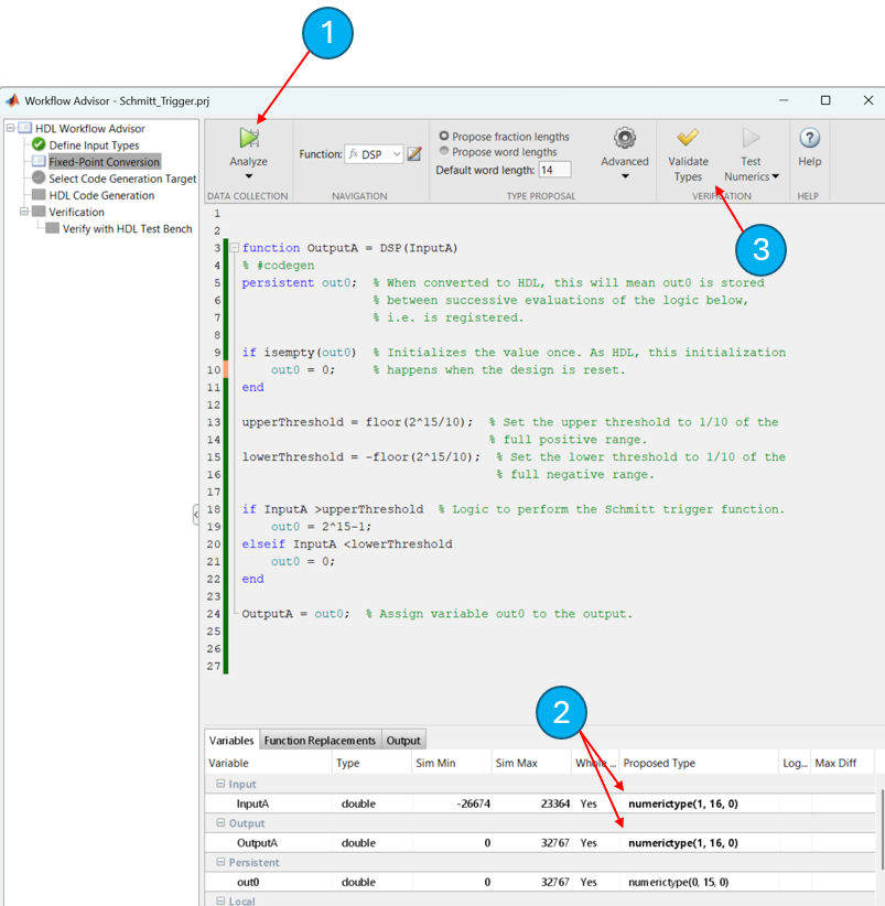
Figure 6: 1. Analyze the data type with testbench input signal. 2. Manually override the data type if necessary. 3. Validate the design and generate the fixed-point model.
Fixed-point model verification
After the fixed-point model conversion, we need to run another simulation to verify that the fixed-point model behaves as expected and evaluate any precision loss. The fixed-point model verification is done through “Test Numerics” button. Make sure to select “Log inputs and outputs for comparison plots”, as this will generate plots to compare the variables in the floating-point model to the same variables in the fixed-point model.
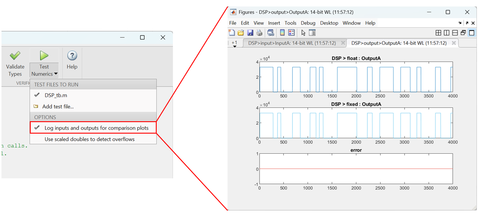
Figure 7: Comparison of the variable OutputA between the floating-point model and fixed-point model
If unacceptable precision losses are observed, increase the variable precision, and then repeat the fixed-point conversion. Please note the precision of Input, Output, and Control signals must match the hardware interface.
Once the fixed-point model passes the verification with testbench, we can proceed to generate the VHDL code for the Schmitt trigger model.
VHDL code generation
Proceed to “Select Code Generation Target” in the menu, we will leave it as “Generic ASIC/FPGA”.
In the “HDL Code Generation” step, we will need to configure the “Target” and “Clocks & Ports”:
- Target:
- Set Language to VHDL
- Clocks & Ports:
- Set Reset type to Synchronous
- Check Minimize clock enables
- Set Input data type to signed/unsigned
- Set Output data type to signed/unsigned
Once we click “Run”, the VHDL code for the system will appear under …\ codegen\DSP\hdlsrc folder.
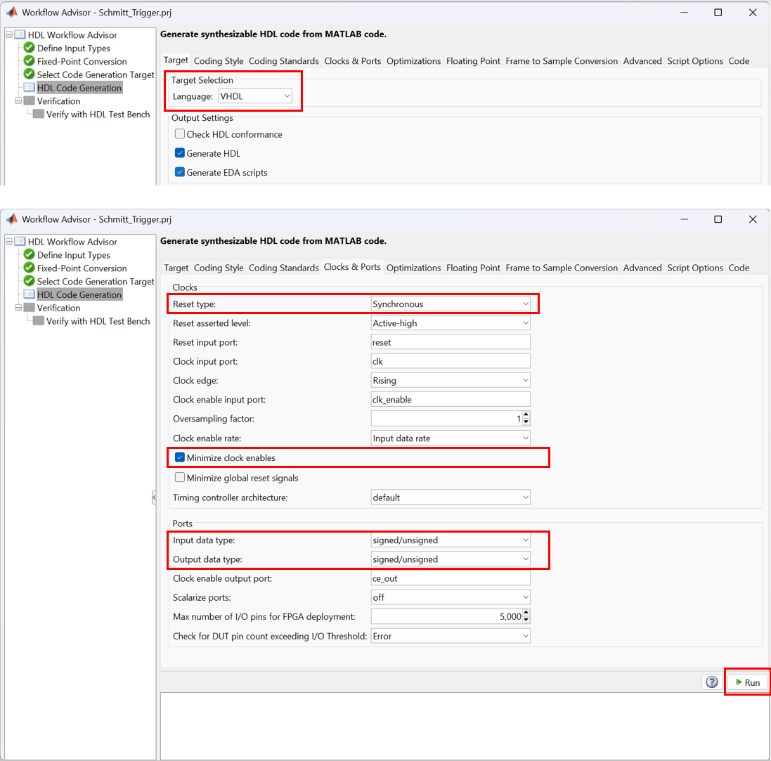
Figure 8: Select the target language to VHDL and run the code generation
VHDL simulation with a third-party tool (optional)
The HDL Coder can also generate HDL testbench files for running simulations on EDA software. Validating the model with a third-party HDL simulator provides an extra layer of insurance for the design. This step is optional but highly recommended for complicated systems. The testbench file can be generated in the “HDL Verification” step of the Workflow Advisor.
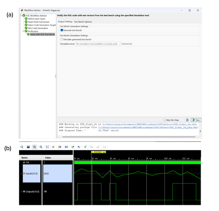
Figure 9: (a) HDL testbench files can be generated in the HDL Coder. (b) HDL level simulation with Xilinx Vivado.
Compile and deployment
Now that we have the VHDL code for our Schmitt trigger, we are ready to compile the instrument using Liquid Instruments’ Moku Cloud Compile and then to deploy on a Moku:Pro.
Instrument wrapper
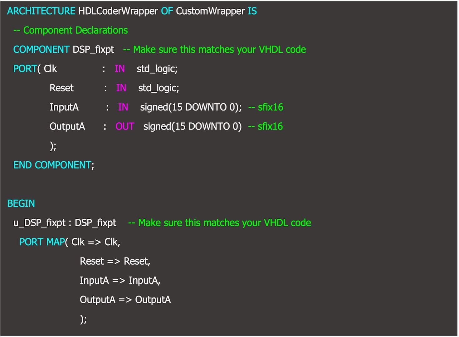
Moku Cloud Compile has a standard wrapper built in to allow custom instruments to interact with the other parts of the Moku. The standard wrapper uses all 4 input channels and output channels for the instrument, this does not match our Schmitt trigger example, which has only 1 input and 1 output. Therefore, we will need to create a custom wrapper for the instrument.
Wrapper templates for MATLAB-generated VHDL code is provided for this tutorial. There are three different wrapper templates provided, one designed for MATLAB HDL Coder-generated VHDL code (i.e., this tutorial), one designed for Simulink-generated VHDL code (i.e., Part II of this tutorial), and finally one for if your code contains a ce-out port. Please inspect the port definition section of your VHDL code before you proceed to select the wrapper template suitable for your application.
Below is the custom wrapper that we will use for compiling the Schmitt trigger instrument.
Compiling and deploying the instrument
Detailed instructions on how to use Moku Cloud Compile to build instrument bitstream and deploy the instrument can be found in our Moku Cloud Compile Getting Started Guide.
To compile the Schmitt trigger, create a new project on Liquid Instruments’ Moku Cloud Compile. In this project, create a file for the DSP_fixpt.vhd, which is the VHDL code for the Schmitt Trigger; also create a wrapper file for the custom wrapper from the previous sections. Select a target device as a Moku:Pro with 4 slots and build the project. Once the bitstream is built, you will be able to deploy the Schmitt Trigger on your Moku:Pro using the web interface and the Moku: app.
To demonstrate the Schmitt trigger is functioning as our conceptual design at the very start, we placed the complied DSP into the system using the Moku: App in the Multi-Instrument Mode. In slot 1, we placed in an Arbitrary Waveform Generator to generate the same signal we have used in the testbench as the input signal to the Schmitt trigger. In slot 2, we placed in our Schmitt trigger. In slot 3, we placed in an Oscilloscope, with Input 1 showing the output from the Schmitt trigger and Input 2 showing the signal output from the Arbitrary Waveform Generator to compare the signals. We can see that the output from the Schmitt trigger switched to high when the signal crossed above 110 mV, it remained high until the signal drops below -110 mV. This confirms the Schmitt trigger is working as designed.
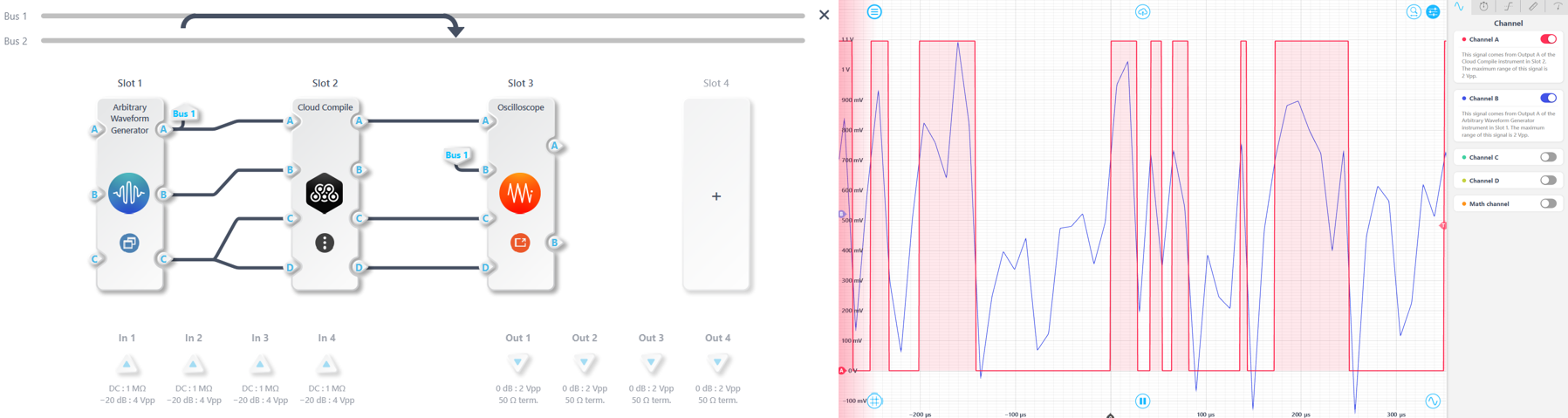
Figure 10: (a) Multi-Instrument system configuration. (b) Oscilloscope measurement verifying the Schmitt trigger is functioning as designed.
Conclusion
This tutorial covered the detailed process of converting a MATLAB script into VHDL code that can be compiled for implementation on Moku platforms. The process involves 4 top level processes: DSP design, floating point simulation, HDL generation, and DSP deployment and verification. This process removes the need to learn HDL programming and enables users to jump straight into designing and creating their own custom instruments.
Code availability
The source code for this project can be downloaded here.
Questions or comments?
Contact us at support@liquidinstruments.com.